Tri-M Systems, Inc. Unit 100, 1407 Kebet way Port Coquitlam, BC V3C 6L3 Canada www.tri-m.com Phone: 604.945.9565 Fax: 604.945.9566 info@tri-m.com FV – 25 USER’S GUIDE This document features the specification of FV-25 and describes the details on using the evaluation kit to evaluate the performance of FV-25 and select the desired functions. It intends to help users to obtain the maximum performance from FV-25 in users’ integrating GPS systems. Version: 1.
Contents Preface………………………………………………………… Chapter 1 Introduction……………………………………….. 1.1 Supports……………………………………………………….. Chapter 2 Start……………………………………………….. 2.1 Pin Definitions and Reference Layout…………………………. 2.2 Sanav_Demo……………………………………………………. 2.2.1 Port Number & Baud Rate………………………………. 2.2.2 Comm Port Connection and Disconnection……………... 2.2.3 Constellation Map………………………………………… 2.2.4 Message View for NMEA Messages……………………… 2.2.5 Available NMEA Messages……………………………….. 2.2.6 GPS Satellite Information………………………………….
4.5 Navigation Data……………………………………………………. 4.5.1 Position Format……………………………………………… 4.5.2 Datums………………………………………………………. 4.5.3 Update Rate………………………………………………….. 4.5.4 Kinematic Mode……………………………………………… 4.6 Navigation for Less Than 4 Observable Satellites…………………… 4.6.1 2D Navigation………………………………………………… 4.6.2 Dead Reckoning………………………………………………. 4.7 Almanac Navigation………………………………………………….. 4.8 DGPS – WAAS, EGNOS, & RTCM…………………………………. 4.9 Receiver Autonomous Integrity Monitoring (RAIM)………………… 4.
List of Figures Figure 2.1 FV-25 Pin definitions (Top View)………………………………….. Figure 2.2 A reference layout for FV-25……………………………………….. Figure 2.3 Setting of comm. port number and the value of baud rate………….. Figure 2.4 Setting of comm. port number………………………………………. Figure 2.5 Setting of the value of baud rate…………………………………….. Figure 2.6 Window after correct setting………………………………………… Figure 2.7 Constellation Map of GPS satellites………………………………… Figure 2.8 Window for showing NMEA messages……………………………… Figure 2.
List of Tables Table 1.1 Specification of FV-25…………………………………………….. Table 2.1 Description of pin definition for FV-25…………………………… Table 4.1 Conditions for Start-Up modes……………………………………. Table 4.2 Available sensitivity modes……………………………………….. Table 7.1 The types of data………………………………………………….. Table 7.2 UBX message classes……………………………………………... Table 8.
Preface The objective of The FV-25 User’s Guide is to help users to understand the properties of FV-25 thoroughly and, therefore, obtain the maximum performance from the module easily. This document describes and provides the useful information the FV-25 module, which includes the functions of pins on the module, configuration setting, utility, and evaluation kit. It will help users understand the capability of the module and, therefore, successfully integrate the FV-25 into users’ GPS systems.
Chapter 7 Available NMEA and UBX1 Messages This chapter lists the available NMEA and u-blox proprietary (UBX) messages for the module. Chapter 8 Troubleshooting This chapter provides good helps when the module isn’t running properly. Appendix A Geodetic ID: Coordinate Datum Appendix B Acronyms In addition to the above brief description for each chapter, you also can find useful definitions for GPS terminologies in the Appendix B as well as the lists of figures (page ?) and tables (page ?).
Chapter 1 Introduction In this chapter, the main goal of FV-25 will be described and then the features of the FV-25 module will be specified in order that a user can make correct decision about module selection before proceeding further development. Understanding thoroughly the pro and con of FV-25 will clear the compatibility of the module with a user’s system. At the same time, let the users make the best performance out the module.
sensitivity for weak signals without sacrificing accuracy, AGPS function, DGPS function which is supported by RTCM, WAAS, and EGNOS, and flexibility for system integrations. Because of 8192 frequency search bins at the same time, it accelerates the start-up times of the module. In addition to the above excellent advantages, FV-25 has the capabilities to perform low power consumption due to the advanced hardware components and implement power saving function owing to versatile firmware.
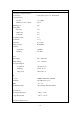
Specification Performance Characteristics Receiver Type L1 frequency, C/A code, 16 Channels Position Accuracy w/o aid 3.3 m CEP DGPS(WAAS, EGNOS,RTCM) 2.6 m AGPS Support Yes Start-up Time Hot start <3s Warm start 35 s Cold start 41 s Reacquisition Time <1s Acceleration <4g Update Rate up to 4 Hz Timing Accuracy 50 ns RMS Sensitivity Acquisition -140 dBm Tracking -149 dBm Power Input Voltage 5.0 ~ 12.0 V DC Backup Voltage 1.95 ~ 3.
Dimension 37.1mm x 25.6 mm Thickness 3.9 mm Weight 9.5 g (include an SMA jack and 5 cm RG-316) Antenna Type External Active or Passive Antenna Input Voltage (VANT) 1.8 V ~ 8 V DC Input Power limit (Active) < -17 dBm Gain (Active) up to 25 dB Supervision Build-in short circuit detection, External open circuit detection Note: For using the passive antenna, Pin VANT has to be connected to GND. Table 1.1 Specification of FV-25.
Chapter 2 Start 2.1 Pin Definitions and Reference Layout Figure 2.1 shows the pin definitions of FV-25. Table 2.1 describes the corresponding definitions for pins. Note that only either use VIN-1 (DC 5 ~ 12V) or VIN-2 (DC 3.3V) for voltage input. Also, if the Pins 1 ~ 10 are used, please leave Pins a ~ n being opened. There are two comm. ports to input/output the useful information (i.e. receiver’s and satellites’ data) for the users. The default setting for comm.
Pin Definitions Pin No. Title I/O Note 1 VANT I 2 VIN-2 I Voltage input 3.3V DC (MUST leave open if VIN-1 is used) 3 Ground I Ground 4 RX2 I Serial port 2 (leave open if not used) 5 TX1 O Serial port 1 (leave open if not used) 6 VIN-1 I Voltage input 5~12V DC (MUST leave open if VIN-2 is used) 7 VBAK I 8 1PPS O Time pulse (leave open if not used) 9 TX2 O Serial port 2 (leave open if not used) 10 RX1 I Serial port 1 (leave open if not used) Pin No.
2.2 Sanav_Demo Sanav_Demo is required to run on a PC with at least 4 MB RAM and Windows 98 that has at least one available serial comm. port (from 1 to 24). 2.2.1 Port Number & Baud Rate When users implement Sanav_Demo, the first window appeared on the screen is the setting of comm. port number and the corresponding value of baud rate, as shown in Figure 2.3. To open or close the “Setting” window, click the selection “File/Port” or the short cut button . Figure 2.3 Setting of comm.
Figure 2.4 Setting of comm. port number. For setting the value of baud rate, pull the scroll-down window for the “Baud rate” item and the desired window shows that the available range of baud rate is from 2400 bps to 115200 bps, as shown in Figure 2.5. The users select the right one that will communicate the module with the host PC. Figure 2.5 Setting of the value of baud rate. 2.2.
subsequent window will be the one shown in Figure 2.6, i.e., the navigation data from the module are displayed in the corresponding sub-windows. If the setting values are not correct or the connection hasn’t established yet, Sanav_Demo will prompt a warning sentence “Comm port couldn’t be open, please check the device”. When a new port setting is required, make sure Sanav_Demo is disconnected from the module before sending the request, i.e.
Figure 2.7 Constellation Map of GPS satellites. 2.2.4 Message View for NMEA Messages Figure 2.8 is the window for showing the desired (user-selected) output NMEA messages. There are two ways to show the “Message View” window. Click the item “Windows/Terminal View” or the shortcut button ?. The default window for “Message View” is only showing the output NMEA messages at current epoch (one epoch), like the one shown in Figure 2.6. Figure 2.8 Window for showing NMEA messages.
accumulatively within the sub-window until the sub-window is filled up, i.e., the “Message View” window contains NMEA messages from several epochs, as shown in Figure 2.9, and the oldest data will be “squeezed” out in the top of the sub-window while the new data will be displayed in the bottom of the sub-window. After clicking the “Show all MS” button, the “Message View” window shows two available buttons: “Current MS” and “Save”.
Figure 2.10 Available NMEA messages. NOTE: The output NMEA messages will be discarded or not transmitted if the values of the baud rate is not sufficient to transmit the desired messages. Also, the discarded part won’t be output in the next epoch. NOTE: The maximum update rate is 4 Hz. 2.2.6 GPS Satellite Information Figure 2.
Figure 2.11 GPS satellite information. 2.2.7 Receiver Information Figure 2.12 describes the receiver information. They are: UTC Date: day/month/year; UTC Time: hour:minute:second; Lat: latitude xxyy.yyyy xx: degree, yy.yyyy: minute, -: southern hemisphere; Lon: longitude xxxyy.yyyy xxx: degree, yy.
Figure 2.12 Receiver Information. NOTE: Data displayed in the sub-windows (Figures 2.7, 2.9, 2.11, and 2.12) depend on the user-selected output NMEA messages, i.e., if, for example, the module doesn’t output GSV message, the associated information, such as elevation, azimuth, SNR, etc., will not be displayed in the corresponding sub-windows. 2.2.8 Tracking View Clicking “Windows/Tracking View”, the global position differences relative to the first position fix will be depicted, as shown in Figure 2.13.
Figure 2.13 Tracking View. 2.2.9 User Setting Clicking “Windows/User Setting” or the shortcut button ?, the “User Setting” window is activated, as shown in Figure 2.14. Click “ ” to move among the tags. 2.2.9.1 Position This function sets the initial latitude and longitude, as shown in Figure 2.14.
The output position will be updated as the position is fixed. 2.2.9.2 Time and day This function sets the initial UTC date and time, as shown in Figure 2.15. The format for UTC date is “YYYY (year), MM (month), DD (day)” and the format for UTC time is “hh (hour), mm (minute), ss (second)”. If a setting value is less than 10, the empty part (the left digit) of the setting value is filled by 0, for instance, 01. Figure 2.15 Initial UTC time and day.
Figure 2.16 Local time zone. 2.2.9.4 Restart This function sets the initial start-up mode, such as cold-start, warm-start, and hot-start, for the module, as shown in Figure 2.17. Figure 2.17 Restart. NOTE: For implementing the hot and warm starts, the module need a backed-up battery to run RTC and support BBR, which is used to save updated position, ephemeris, and almanac data.
2.2.9.5 DGPS This function activates the differential GPS functions of the module, such as RTCM and WAAS/EGNOS, or only GPS function without aids, as shown in Figure 2.18. Figure 2.18 DGPS. 2.2.9.6 Interval Referred to Section 2.2.5. 2.2.9.7 Geodetic ID This function sets coordinate datum that users prefer, as shown in Figure 2.19. A list of datum ID is summarized in the Appendix A. Figure 2.19 Setting of coordinate datum.
Chapter 3 Alternative Start This chapter introduces an alternative utility, HyperTerminal (from Windows), to display the NMEA information. And, Using the utility, users can send a request to poll the desired NMEA information or implement other configurations from the module without the aid of Sanav_Demo. The following information only describes the needed operations for our purposes. 3.
the mode of connection. Figure 3.2 Connection settings. After setting all the necessary data, click the connection button, which is the fifth shortcut button from right. If the setting is correct, the HyperTerminal window will show desired output (NMEA messages), as shown in Figure 3.3, and if not, the window will show random characters or nothing at all. Figure 3.3. Correct connection settings. 3.2 Saving the Data For saving the output data, click “Transfer/Capture Text…”.
will ask users to input the file name and folder. 3.3 Setting Configuration or Polling Information from Module For setting or polling the desired information, click “Transfer/Send Text File…” button to send a “.txt” file, which contains command sentences, to activate the module. The file is created by users before click the button, and the formats for the command sentences are referred to Chapter 7.
Chapter 4 Navigation 4.1 Operating Modes 4.1.1 Continuous Tracking Mode (CTM) CTM is the default setting of the module. While the CTM is on, the module tracks GPS signals and estimates position continuously, i.e., satellite acquisition, reacquisition, and tracking are the states in the CTM. This is the standard operating mode for the general GPS receivers. Therefore, this mode is not designed for saving power but for obtaining maximum accuracy in position.
Conditions Modes Time Position Almanac Ephemeris Cold Start None None None None Warm Start Yes Yes Yes None Hot Start Yes Yes Yes Yes Table 4.1 Conditions for Start-Up modes. For the cold-start mode, the module assigns all the available SVs to 16 channels in a defaulted order. As a satellite is acquired, GPS time, associated ephemeris and almanac data, which will take 12.
will improve on TTFF depends on the accuracy of position and time from a near base station (service center) as well as hardware synchronization. The AGPS function of the module is activated by sending u-blox binary protocol UBX-AID-REQ. If there is no data available from a near base station, the module is back to its normal start-up modes. 4.4 Sensitivity There are three modes available for the module, which are “Normal”, “Fast Acquisition” and “High Sensitivity”. Table 4.
dB is used, the “High Sensitivity” mode is not recommended. 4.5 Navigation Data 4.5.1 Position Format The navigation data can be output in the format of local geodetic frame (latitude, longitude, and altitude), ECEF (Earth-Centered Earth-Fixed) frame, or Universal Transverse Mercator (UTM) frame. To poll the navigation information from the module, send the request UBX-CFG-NAV.
initial/assumed value of the altitude is 500 m. If the 2D position fix occurs after the 3D position fix (number of observable satellites drops from at least 4 to 3), the value of the altitude will keep the last known value of the altitude from the previous 3D position fix. 4.6.2 Dead Reckoning As the module loses the tracks for all observable GPS signals because of, for example, an external blockage, the navigation algorithm implements the Dead Reckoning strategy.
RTCM protocol, please refer to the web site http://www.rtcm.org/. The DGPS parameters can be changed in the UBX-CFG-NAV message, like DGPS Timetag Rounding. Do not change them under no specific reasons because the default values are based on real tests with DGPS function. NOTE: The correction data from the RTCM messages can be monitored by the UBX-NAV-DGPS message, which doesn’t provide the supervision on WAAS and EGNOS. 4.
Chapter 5 Evaluation Kit The evaluation kit is an optional accessory while purchasing the module. It will provide an easy way to estimate the performance of our module. The users can also follow the reference circuit design in Chapter 2 to test the performance of the module. In this chapter, all the information about the evaluation kit, which includes the output ports, buttons, and LED lights, is described.
re-start up the GPS module in the either Continuous Tracking Mode or FixNow mode. Figure 5.2 Front panel of the evaluation kit. Figure 5.3 shows the back panel of the evaluation kit. It includes (from left to right) the Antenna Input, Comm. Port 1, 1PPS Output, and Power Input. The Antenna Input is a SMA female connecter which is for 3.0 V or 5.0 V active antenna depending on the jump position (J16). The Comm. Port 1 outputs NMEA messages at the baud rate of 19200 bps as the default setting.
Both Comm. ports are the bi-directional ports, i.e., the ports also accepts user software commands. For receiving RTCM message, either port can be used to accept the data through software command.
Chapter 6 Antennas To get the maximum performance from the module, in addition to the own properties of the module, one of the important factors is how to select fitted antennas for the module because the quality of the received signals is determined as soon as the signals enter the RF section and can not be improved much by the subsequent filters and amplifiers. The character of the GPS signal is right hand circular polarized (RHCP).
For using passive antennas, the pin VANT (DC bias voltage) on the module is connected to ground, and the antenna is directly connected to the GPS signal input pin ANT. Sometimes, a passive matching connection is required to match the electrical circuit to 50 Ohms impedance. 6.2 Active Antennas For FV-25, the active antenna is integrated with a Low Noise Amplifier (LNA), which is a built-in component part, in the RF section. Through pin ANT, the module obtains the incoming signal from the antenna.
6.3 Active Antenna Supervisor - Short Circuit Protection This is a built-in function that is monitored by the BaseBand processor. If an abnormal current occurs and is detected, the voltage supply at pin VANT (from the external or internal power supply) will be turned off by the BaseBand processor. The way to reset the operation of the module is to have a hardware reset of the module, such as turning off and then on the module or pressing the reset button.
Chapter 7 Available NMEA and UBX Messages 7.1 NMEA Protocol The NMEA protocol expresses the data in the format of ASCII. This is a standard format for GPS applications. The module (FV-25) outputs two types of NMEA messages. One is the standard NMEA messages, that are widely accepted by plotters and GPS related devices, and the other is u-blox proprietary NMEA messages. 7.1.
the “PDOP Accuracy Mask”.
GGA – GPS Fix Data Position fix related data, such as position, time, number of satellites in use, etc.. $GPGGA,gga1,gga2,gga3,gga4,gga5,gga6,gga7,gga8,gga9,gga10,gga11,gga12,gga 13,gga14*hh Parameters Descriptions Notes gga1 UTC time as position is fixed hhmmss.ss: hh – hour; mm – minute; ss.ss – second gga2 Latitude ddmm.mmmmm: dd – degree; mm.mmmmm – minute (0o ~ 90o) gga3 Latitude sector N – North; S - South gga4 Longitude dddmm.mmmmm: dd – degree; mm.
GLL – Geographic Position – Latitude/Longitude Navigation data and status. $GPGLL,gll1,gll2,gll3,gll4,gll5,gll6,gll7*hh Parameters Descriptions Notes gll1 Latitude ddmm.mmmmm: dd – degree; mm.mmmmm – minute (0o ~ 90o) gll2 Latitude sector N – North; S – South gll3 Longitude dddmm.mmmmm: ddd – degree; mm.mmmmm – minute (0o ~ 180o) gll4 Longitude sector E – East; W – West gll5 UTC time as position is fixed hhmmss.ss: hh – hour; mm – minute; ss.
GRS – GNSS Range Residual This message is used to monitor and support RAIM. $GPGRS,grs1,grs2,(grs3*12)*hh Parameters Descriptions Notes grs1 UTC time from the GGA grs2 Mode to indicate the way to calculate Always in Mode 1 the range residuals. 0 – calculate the range residuals while the GGA position is estimated; 1 – recalculate the range residuals after the GGA position is estimated. grs3*12 hh hhmmss.ss: hh – hour; mm – minute; ss.
GSA – GNSS DOP and Active Satellites Receiver operating mode, the values of DOPs, and PRN numbers for satellites used in the GGA position solution. $GPGSA,gsa1,gsa2,(gsa3*12),gsa4,gsa5,gsa6*hh Parameters Descriptions Notes gsa1 gsa2 gsa3*12 Mode for position fix 1 – fix not available; 2 – 2D; 3 – 3D; PRN numbers for satellites used in the xx position solution. There will be 12 available fields for PRN numbers.
GST – GNSS Pseudorange Error Statistics This message is used to monitor and support RAIM.
GSV – GNSS Satellites in View This message indicates the observable satellites’ information, such as PRN numbers, elevation, azimuth, SNR, and number of satellites in view.
RMC – Recommended Minimum Specific GNSS Data This message transmits the necessary navigation data, such as time, position, speed, course, and so on. $GPRMC,rmc1,rmc2,rmc3,rmc4,rmc5,rmc6,rmc7,rmc8,rmc9,rmc10,rmc11,rmc 12*hh Parameters Descriptions Notes rmc1 UTC time as position is fixed hhmmss.ss: hh – hour; mm – minute; ss.ss – second rmc2 Status of position fix A – data valid, which includes the scenarios of 2D, 3D, and DR. V – navigation receiver warning rmc3 Latitude ddmm.
TXT – Text Transmission The message is used to transmit short text messages. Transmitting a longer message needs multi-TXT messages.
VTG – Course Over Ground and Ground Speed This message transmits the speed and course relative to ground. $GPVTG,vtg1,vtg2,vtg3,vtg4,vtg5,vtg6,vtg7,vtg8,vtg9*hh Parameters Descriptions Notes vtg1 Course over ground (degrees) Referenced to true north (000.00o ~ 359.99o) vtg2 Indicator of course reference T – true north vtg3 Course over ground (degrees) Referenced to magnetic north (000.00o ~ 359.
ZDA – Time & Date This message transmits UTC time and date, and local time zone. $GPZDA,zda1,zda2,zda3,zda4,zda5,zda6*hh Parameters Descriptions Notes zda1 UTC time hhmmss.ss: hh – hour; mm – minute; ss.
7.1.2 Proprietary NMEA Messages The non-standard NMEA messages is proposed by u-blox. The proprietary (non-standard) NMEA messages are grouped into two categories: Proprietary NMEA (PUBX) PUBX,00 – Latitude/Longitude Position Data PUBX,01 – UTM Position Data PUBX,03 – Satellite Status PUBX,04 – Time of Day and Clock Information PUBX,40 – Set NMEA Message Update Rate PUBX,41 – Set Protocols and Baudrate Queries GPQ – Polls a Standard NMEA Message PUBX – Polls a PUBX Message.
PUBX, 00 – Latitude/Longitude Position Data Output message. This message transmits navigation data defined in the local geodetic frame. $PUBX,00,p00x1,p00x2,p00x3,p00x4,p00x5,p00x6,p00x7,p00x8,p00x9,p00x10,p0 0x11,p00x12,p00x13,p00x14,p00x15,p00x16,p00x17,p00x18,p00x19*hh Parameters Descriptions Notes p00x1 UTC time hhmmss.ss: hh – hour; mm – minute; ss.ss – second p00x2 Latitude ddmm.mmmmm: dd – degree; mm.
the position calculation p00x18 Number of GLONASS satellites Always 0 used in the position calculation p00x19 Dead reckoning used 0 – No; 1 – Yes Checksum hex number (2 – character) hh End of message 55
PUBX, 01 – UTM Position Data Output message. This message transmits navigation data defined in the Universal Transverse Mercator (UTM) frame. $PUBX,01,p01x1,p01x2,p01x3,p01x4,p01x5,p01x6,p01x7,p01x8,p01x9,p01x10,p0 1x11,p01x12,p01x13,p01x14,p01x15,p01x16,p01x17,p01x18,p01x19*hh Parameters Descriptions Notes p01x1 UTC time hhmmss.ss: hh – hour; mm – minute; ss.
used in the position calculation p01x19 hh Dead reckoning used 0 – No; 1 – Yes Checksum hex number (2 – character) End of message 57
PUBX,03 – Satellite Status Output message. $PUBX,03,p03x1,((p03x2,p03x3,p03x4,p03x5,p03x6,p03x7)*n)*hh Parameters Descriptions Notes p03x1 Number of GPS satellites tracked p03x2 PRN number 01 ~ 32 p03x3 Satellite status - – not used U – used e – available for navigation, but no ephemeris p03x4 Azimuth (degrees) 000 ~ 359 p03x5 Elevation (degrees) 00 ~ 90 p03x6 SNR (dB-Hz) 00 ~ 55 p03x7 Carrier lock time (seconds) 0 ~ 255 0: code lock only; 255: lock time at least 255 seconds.
PUBX,04 – Time of Day and Clock Information Output message. This message transmits UTC time, week number, and clock offset. $PUBX,04,p04x1,p04x2,p04x3,p04x4,p04x5,p04x6,p04x7,p04x8*hh Parameters Descriptions Notes p04x1 UTC time hhmmss.ss: hh – hour; mm – minute; ss.
GPQ – Poll Message Input message. Poll a standard NMEA message.
PUBX – Poll a PUBX Message Input message. Poll the proprietary PUBX messages.
PUBX,40 – Set NMEA Message Output Rate Input message.
PUBX,41 – Set Protocols and Baudrate Input message.
7.2 UBX Binary Protocol To obtain the maximum performance from GPS chips, which mainly consists of FV-25, u-blox proposed a proprietary binary protocol. The binary protocol can set and poll all the available actions and messages from the module. Using asynchronous RS232 ports, the module communicates with a host platform in terms of the alternative, UBX protocol, to carry GPS data. The noticeable features for the UBX protocol are 1. 8 bits binary data; 2. low-overhead checksum algorithm; 3.
For the calculation of the checksum, u-blox utilizes the low-overhead checksum algorithm, which is the TCP standard (RFC 1145). The calculation of the checksum covers the range from the CLASS ID byte (included) to DATA bytes (included). It can be described as CK_A=0; CK_B=0; for(i = 0;i < N;i ++) { CK_A += buffer[i]; CK_B += CK_A; } where CK_A and CK_B: 8-bit unsigned integers; buffer[•]: vector that contains the data in the calculating range (i.e.
R8 IEEE754 Double Precision 8 CH ASCII / ISO 8859.1 Encoding 1 -1*21023 ~ 21023 ~Value*2-53 Table 7.1 The types of data. 7.2.2 Classification of UBX Messages The u-blox proprietary messages are classified into 9 groups. Based on a specific topic, each group contains the associated information. They are summarized in Table 7.2.
7.2.4 UBX Messages UBX Class ACK This class is used for responding a CFG message. ACK – ACK (0x05 0x01) Message acknowledged.
ACK – NAK (0x05 0x00) Message not-acknowledged.
UBX Class AID This class is used to support AGPS function or send aiding data, such as time, position, almanac, and ephemeris, to the GPS receiver. AID – REQ (0x0B 0x00) It’s a virtual request to poll all GPS aiding data (AID-DATA). The character of AID-REQ is determined by CFG-MSG. If AID-REQ is set as the output message and the internal stored data (i.e.
AID – DATA (0x0B 0x10) It’s a request to poll all the GPS initial aiding data. This message will activate the sending of AID-INI, AID-HUI, AID-EPH, and AID-ALM as it is received by the module.
AID – INI (0x0B 0x01) It’s a poll request when “data length” is equal to 0. Poll GPS initial aiding data. Header ID Data Length Data Checksum 0xB5 0x62 0x0B 0x01 0 None CK_A CK_B AID – INI (0x0B 0x01) This is an I/O message. It contains the information of position and time. As an output message, the value of the clock drift is always 0 and assigned invalid.
AID – HUI (0x0B 0x02) It’s a poll request when “data length” is equal to 0. Poll GPS health, UTC, and Ionosphere data. Header ID Data Length Data Checksum 0xB5 0x62 0x0B 0x02 0 None CK_A CK_B AID – HUI (0x0B 0x02) It’s an I/O message. It transmits GPS health, UTC, and Ionosphere (Klobuchar parameters) data.
48 R4 Alpha3 Klobuchar parameters 52 R4 Beta0 Klobuchar parameters 56 R4 Beta1 Klobuchar parameters 60 R4 Beta2 Klobuchar parameters 64 R4 Beta3 Klobuchar parameters 68 U4 Flag3 0x1 – valid health bit mask fields 0x2 – valid UCT parameter fields 0x4 – valid Klobuchar parameter fields 73
AID – ALM (0x0B 0x30) It’s a poll request when “data length” is equal to 0. Poll all available aiding almanac data. Header ID Data Length Data Checksum 0xB5 0x62 0x0B 0x30 0 None CK_A CK_B AID – ALM (0x0B 0x30) It’s also a poll request. Poll a specific aiding almanac data.
28 U4 Almanac – WORD5 32 U4 Almanac – WORD6 36 U4 Almanac – WORD7 NOTE: 1. WORD0 ~ WORD7 contain the data following the Hand-Over Word (HOW) in the navigation message. The data are from the sub-frame 4 of Pages 1 ~ 24 and the sub-frame 5 of Pages 2 ~ 10. More information about almanac data structure is referred to ICD-GPS-200. 2. WORD0 ~ WORD7 don’t include the data of the parity bits. Hence, Bits 0 ~ 23 is used to locate the 24 bits of the data and Bits 24 ~ 31 are the sign-extension of the data.
AID – EPH (0x0B 0x31) It’s a poll request when “data length” is equal to 0. Poll all available aiding ephemeris data. Header ID Data Length Data Checksum 0xB5 0x62 0x0B 0x31 0 None CK_A CK_B AID – EPH (0x0B 0x31) It’s also a poll request. Poll a specific aiding ephemeris data.
32+n*96 U4 Sub-frame 1 – WORD6 36+n*96 U4 Sub-frame 1 – WORD7 40+n*96 U4 Sub-frame 2 – WORD0 44+n*96 U4 Sub-frame 2 – WORD1 48+n*96 U4 Sub-frame 2 – WORD2 52+n*96 U4 Sub-frame 2 – WORD3 56+n*96 U4 Sub-frame 2 – WORD4 60+n*96 U4 Sub-frame 2 – WORD5 64+n*96 U4 Sub-frame 2 – WORD6 68+n*96 U4 Sub-frame 2 – WORD7 72+n*96 U4 Sub-frame 3 – WORD0 76+n*96 U4 Sub-frame 3 – WORD1 80+n*96 U4 Sub-frame 3 – WORD2 84+n*96 U4 Sub-frame 3 – WORD3 88+n*96 U4 Sub-frame 3 – WORD4 92
UBX Class CFG This class is used to configure the GPS module and output the current configuration of the GPS module. The module will respond the ACK-ACK message if the request is proceeded correctly and ACK-NAK message if the request is failed. CFG – PRT (0x06 0x00) It’s a poll request. Poll the current configuration for a specific comm. port.
10 – 2 stop bit ; 11 – reserved Bit[16] 0 – LSB first bit order 1 – MSB first bit order Bit[19] 0 – 16x oversampling 1 – 8x oversampling 8+N*20 U4 Baud rate (bps) 12+N*20 U2 Input protocol for a single port. Bit mask Multi-protocols can be selected 0x0001 – UBX protocol for a single port. 0x0002 – NMEA protocol 0x0004 – RTCM protocol 0x1000 – User0-defined protocol 0x2000 – User1-defined protocol 0x4000 – User2-defined protocol 0x8000 – User3-defined protocol The rest of bits are reserved.
CFG – MSG (0x06 0x01) It’s a poll request. Poll a message configuration. Header ID Data Length Data Checksum 0xB5 0x62 0x06 0x01 2 See below CK_A CK_B Data Offset bytes Format Descriptions 0 U1 Class ID 1 U1 Message ID Notes CFG – MSG (0x06 0x01) It’s an I/O message. As an input message, the message rate configurations for several targets can be put together into one input sentence. As an output message, the message only transmits one message rate configuration from one target.
Data Offset bytes Format Descriptions 0 U1 Class ID 1 U1 Message ID 2 U1 Message rate on the current target 81 Notes
CFG – NMEA (0x06 0x17) It’s a poll request. Poll the NMEA protocol configuration. Header ID Data Length Data Checksum 0xB5 0x62 0x06 0x17 0 None CK_A CK_B CFG – NMEA (0x06 0x17) It’s an input message. Set the desired NMEA protocol. Header ID Data Length Data Checksum 0xB5 0x62 0x06 0x17 4 See below CK_A CK_B Data Offset bytes Format 0 U1 Descriptions Filtering. Disable or not.
CFG – RATE (0x06 0x08) It’s a poll request. Poll the current navigation/measurement rate setting. The module will respond the same message defined below (I/O message). Header ID Data Length Data Checksum 0xB5 0x62 0x06 0x08 0 None CK_A CK_B CFG – RATE (0x06 0x08) It’s an I/O message. It polls or sets the navigation/measurement rate. Header ID Data Length Data Checksum 0xB5 0x62 0x06 0x08 6 See below CK_A CK_B Data Offset bytes Format Descriptions Notes 0 U2 Measurement rate (ms).
CFG – CFG (0x06 0x09) It’s a command message. The message will clear, save, and load configurations. The command consists of the three masks (clear, save, and load) in each individual bit. Header ID Data Length Data Checksum 0xB5 0x62 0x06 0x09 12 See below CK_A CK_B Data Offset bytes Format 0 U4 Descriptions Notes Clear configurations Load factory defaults to active settings. See below for bit settings to definitions.
UBX-CFG-ANT) 11 Reserved 12 ~ 15 Reserved for user applications 16 ~ 31 Reserved 85
CFG – TP (0x06 0x07) It’s a poll request. Poll time pulse information. The module will respond the same message defined below (I/O message). Header ID Data Length Data Checksum 0xB5 0x62 0x06 0x07 0 None CK_A CK_B CFG – TP (0x06 0x07) It’s an I/O message. Poll and set time pulse information. Header ID Data Length Data Checksum 0xB5 0x62 0x06 0x07 20 See below CK_A CK_B Data Offset bytes Format Descriptions 0 U4 Time interval for time pulse Notes (us).
CFG – NAV (0x06 0x03) It’s a poll request. Poll engine settings for navigation. The module will respond the same message defined below (I/O message). Header ID Data Length Data Checksum 0xB5 0x62 0x06 0x03 0 None CK_A CK_B CFG – NAV (0x06 0x03) It’s an I/O message. Poll and set engine settings for navigation.
used in the navigation solution 6 U1 DGPS timetag rounding 1 – enable 0 – disable 7 U1 Timeout for differential correction data (s) 8 U1 Timeout for pseudorange correction data (s) 9 U1 Timeout for carrier phase correction data (s) 10 U2 Carrier Lock Time (CLT): conditional lower limit (ms) 12 U2 CLT: absolute lower limit (ms) 14 U1 Epochs for DR 15 U1 Navigation options Bit mask 0x01 – enable pseudorange check 0x02 – enable Doppler check 0x04 – enable Delta range chec
CFG – DAT (0x06 0x06) It’s a poll request. Poll datum setting. The module will respond the same message defined below (I/O message). Header ID Data Length Data Checksum 0xB5 0x62 0x06 0x06 0 None CK_A CK_B CFG – DAT (0x06 0x06) It’s an input message. Set the standard datum. Header ID Data Length Data Checksum 0xB5 0x62 0x06 0x06 2 See below CK_A CK_B Data Offset bytes Format 0 U2 Descriptions Datum number Notes Referred to Appendix A CFG – DAT (0x06 0x06) It’s an input message.
seconds) 40 R4 Scale change (ppm) 0.0 ~ 50.0 CFG – DAT (0x06 0x06) It’s an output message. Poll the current datum. If the datum number is –1, the module is using the user-defined datum and only the value for semi-major axis is valid and the rest of them are not valid. Header ID Data Length Data Checksum 0xB5 0x62 0x06 0x06 52 See below CK_A CK_B Data Offset bytes Format 0 U2 2 CH[6] 8 Descriptions Notes Datum number Datum name ASCII format R8 Semi-major axis (m) 6,300,000.
CFG – INF (0x06 0x02) It’s a poll request. It’s used to identify the output protocol.
13 – User1-defined protocol 14 – User2-defined protocol 15 – User3-defined protocol 16 ~ 255 – reserved 1+N*8 U1 Reserved 2+N*8 U2 Reserved 4+N*8 U1 Information message enabled Bit mask.
CFG – RST (0x06 0x04) It’s an input message. It’s used to reset receiver or clear backup data structure.
CFG – RXM (0x06 0x11) It’s a poll request. It’s used to poll RXM configuration. The module responds the same message defined below. Header ID Data Length Data Checksum 0xB5 0x62 0x06 0x11 0 None CK_A CK_B CFG – RXM (0x06 0x11) It’s an I/O message. It’s used to set/get RXM configuration.
CFG – ANT (0x06 0x13) It’s a poll request. It’s used to poll antenna control settings. The module responds the same message defined below. Header ID Data Length Data Checksum 0xB5 0x62 0x06 0x13 0 None CK_A CK_B CFG – ANT (0x06 0x13) It’s an I/O message. It’s used to set/get antenna control settings.
CFG – FXN (0x06 0x0E) It’s a poll request. It’s used to poll power saving (FixNow) mode configuration. The module responds the same message defined below. Header ID Data Length Data Checksum 0xB5 0x62 0x06 0x0E 0 None CK_A CK_B CFG – FXN (0x06 0x0E) It’s a command message. It’s used to configure the FixNow mode. It is enabled by the CFG-RXM message.
CFG – SBAS (0x06 0x16) It’s a command message. It’s used to configure SBAS systems, such as WAAS, EGNOS, and MSAS. More information about SBAS services is referred to document RTCA/DO-229C (www.rtca.org). Header ID Data Length Data Checksum 0xB5 0x62 0x06 0x16 8 See below CK_A CK_B Data Offset bytes Format 0 U1 Descriptions SBAS mode.
CFG – TM (0x06 0x10) It’s a poll request. It’s used to poll time mark configuration. Header ID Data Length Data Checksum 0xB5 0x62 0x06 0x10 0 None CK_A CK_B CFG – TM (0x06 0x10) It’s an I/O message. It’s used to set/get time mark configuration.
CFG – EKF (0x06 0x12) It’s a poll request. It’s used to poll EKF configuration. The module responds the same message defined below. Header ID Data Length Data Checksum 0xB5 0x62 0x06 0x12 0 None CK_A CK_B CFG – EKF (0x06 0x12) It’s an I/O message. It’s used to set/get EKF configuration.
2 U1 Reserved 3 U1 Inverse_flags Bit 0 – invert meaning of direction pin; 0: High=Forwards; 1: High=Backwards Bit 1 – invert meaning of gyro rotation positive; sense; 1: 0: clockwise counterclockwise positive 4 U4 Reserved Always 0 8 U2 Nominal pulses per kilometer 1100 ~ 45000 10 U2 Nominal gyro zero point output 2000 ~ 3000 (mV) 12 U1 Nominal gyro sensitivity 20 ~ 40 (mV/(deg/s)) 13 U1 Maximum allowable RMS For zero velocity temperature threshold (mV) compensation: 1 ~ 10
UBX Class INF Basically, the INF class is an output class. It outputs strings with a printf-style call. INF – ERROR (0x04 0x00) It outputs an ASCII string to indicate error message. Header ID Data Length Data Checksum 0xB5 0x62 0x04 0x00 N*1 See below CK_A CK_B Data Offset bytes Format Descriptions The following data will be repeated N times (variable length).
INF – WARNING (0x04 0x01) It outputs an ASCII string to indicate warning message. Header ID Data Length Data Checksum 0xB5 0x62 0x04 0x01 N*1 See below CK_A CK_B Data Offset bytes Format Descriptions The following data will be repeated N times (variable length).
INF – NOTICE (0x04 0x02) It outputs an ASCII string to transmit informational contents. Header ID Data Length Data Checksum 0xB5 0x62 0x04 0x02 N*1 See below CK_A CK_B Data Offset bytes Format Descriptions The following data will be repeated N times (variable length).
INF – TEST (0x04 0x03) It outputs an ASCII string to indicate test message. Header ID Data Length Data Checksum 0xB5 0x62 0x04 0x03 N*1 See below CK_A CK_B Data Offset bytes Format Descriptions The following data will be repeated N times (variable length).
INF – DEBUG (0x04 0x04) It outputs an ASCII string to indicate debug message. Header ID Data Length Data Checksum 0xB5 0x62 0x04 0x04 N*1 See below CK_A CK_B Data Offset bytes Format Descriptions The following data will be repeated N times (variable length).
INF – USER (0x04 0x07) It outputs an ASCII string to indicate user output message. Header ID Data Length Data Checksum 0xB5 0x62 0x04 0x07 N*1 See below CK_A CK_B Data Offset bytes Format Descriptions The following data will be repeated N times (variable length).
UBX Class MON This message is used to transmit GPS receiver status, such as CPU status, I/O status, etc.. MON – SCHD (0x0A 0x01) It periodically polls the status of system scheduler.
MON – IO (0x0A 0x02) It periodically polls the I/O status. Header ID Data Length Data Checksum 0xB5 0x62 0x0A 0x02 80 See below CK_A CK_B Data Offset bytes Format Descriptions Notes The following data will be repeated four times (N = 4).
MON – MAGPP (0x0A 0x06) It periodically polls message parse and process status.
MON – RXBUF (0x0A 0x07) It periodically polls the status of receiver buffer.
MON – TXBUF (0x0A 0x08) It periodically polls the status of transmitter buffer.
MON – VER (0x0A 0x04) It is used to poll the hardware/software version. Header ID Data Length Data Checksum 0xB5 0x62 0x0A 0x04 40+N*30 See below CK_A CK_B Data Offset bytes Format Descriptions 0 CH[30] Software version 30 CH[10] Hardware version The following data will be repeated N times.
UBX Class NAV The messages in this class transmit navigation data, status flags, and accuracy information. NAV – POSECEF (0x01 0x01) It periodically polls the receiver’s position in the ECEF frame.
NAV – POSLLH (0x01 0x02) It periodically polls the receiver’s position in the local geodetic frame.
NAV – POSUTM (0x01 0x08) It periodically polls the receiver’s position in the UTM frame. Header ID Data Length Data Checksum 0xB5 0x62 0x01 0x08 18 See below CK_A CK_B Data Offset bytes Format Descriptions Notes 0 U4 GPS time of week (ms) 4 I4 Easting component (cm) In the UTM frame 8 I4 Northing component (cm) In the UTM frame 12 I4 Altitude (cm) In the UTM frame 16 I1 UTM zone number 17 I1 Hemisphere sector 0 – north 1 – south NOTE: 1. Doesn’t output zone characters (i.
NAV – DOP (0x01 0x04) It periodically polls the values of DOPs. Header ID Data Length Data Checksum 0xB5 0x62 0x01 0x04 18 See below CK_A CK_B Data Offset bytes Format Descriptions 0 U4 GPS time of week (ms) 4 U2 GDOP Geometric DOP 6 U2 PDOP Positional DOP 8 U2 TDOP Time DOP 10 U2 VDOP Vertical DOP 12 U2 HDOP Horizontal DOP 14 U2 NDOP Northing DOP 16 U2 EDOP Easting DOP NOTE: All have Scaling 0.01.
NAV – STATUS (0x01 0x03) It periodically polls navigation status.
NAV – SOL (0x01 0x06) It periodically polls the information about navigation solution.
NAV – VELECEF (0x01 0x11) It periodically polls velocity solution in the ECEF frame.
NAV – VELNED (0x01 0x12) It periodically polls velocity solution in the NED frame.
NAV – TIMEGPS (0x01 0x20) It periodically polls the information about GPS time.
NAV – TIMEUTC (0x01 0x21) It periodically polls the information about UTC time.
NAV – CLOCK (0x01 0x22) It periodically polls receiver clock information.
NAV – SVINFO (0x01 0x30) It periodically polls the information about UTC time. Header ID Data Length Data Checksum 0xB5 0x62 0x01 0x30 8+N*12 See below CK_A CK_B Data Offset bytes Format Descriptions 0 U4 GPS time of week (ms) 4 U1 Number of channels 5 U1 Reserved 6 U2 Reserved Notes 1 ~ 16 The following data will be repeated N times (number of channels).
NAV – DGPS (0x01 0x31) It periodically polls DGPS correction data that are used in the navigation solution.
NAV – SBAS (0x01 0x32) It periodically polls the status of SBAS. Header ID Data Length Data Checksum 0xB5 0x62 0x01 0x32 12+N*12 See below CK_A CK_B Data Offset bytes Format Descriptions 0 U4 GPS time of week (ms) 4 U1 PRN number for SBAS, e.g. Notes WAAS, EGNOS.
17+N*12 U1 Reserved 18+N*12 I2 Pseudo range correction (cm) 20+N*12 I2 Reserved 22+N*12 I2 Ionosphere correction (cm) 127
UBX Class RXM This class transmits the status of receiver manager and received raw data, e.g. pseudorange and carrier phase measurements, ephemeris, and almanac data. RXM – RAW (0x02 0x10) It periodically outputs raw measurement data. It defines all the necessary data for a RINEX file.
RXM – SFRB (0x02 0x11) It periodically outputs the data in the subframe of navigation message.
RXM – SVSI (0x02 0x20) It periodically polls the information of SV status. Header ID Data Length Data Checksum 0xB5 0x62 0x02 0x20 8+N*6 See below CK_A CK_B Data Offset bytes Format Descriptions 0 I4 GPS time of week (ms) 4 I2 GPS week number 6 U1 Number of observable satellites 7 U1 Number of satellite Notes data following The following data will be repeated N times (number of satellites).
RXM – ALM (0x02 0x30) It’s an input request for polling almanac data. The receiver responds with all available (32) RXM-ALM messages defined below. Header ID Data Length Data Checksum 0xB5 0x62 0x02 0x30 0 None CK_A CK_B RXM – ALM (0x02 0x30) It’s an input request for polling almanac data of one specific SV. The receiver responds with a RXM-ALM message defined below.
not valid. 2. WORD0 ~ WORD7 contain the data following the Hand-Over Word (HOW) in the navigation message. The data are from the sub-frame 4 of Pages 1 ~ 24 and the sub-frame 5 of Pages 2 ~ 10. More information about almanac data structure is referred to ICD-GPS-200. 3. WORD0 ~ WORD7 don’t include the data of the parity bits. Hence, Bits 0 ~ 23 is used to locate the 24 bits of the data and Bits 24 ~ 31 are the sign-extension of the data.
RXM – EPH (0x02 0x31) It’s an input request for polling ephemeris data. The receiver responds with all available RXM-EPH messages defined below. Header ID Data Length Data Checksum 0xB5 0x62 0x02 0x31 0 None CK_A CK_B RXM – EPH (0x02 0x31) It’s an input request for polling ephemeris data of one specific SV. The receiver responds with a RXM-EPH message defined below.
36+n*96 U4 Sub-frame 1 – WORD7 40+n*96 U4 Sub-frame 2 – WORD0 44+n*96 U4 Sub-frame 2 – WORD1 48+n*96 U4 Sub-frame 2 – WORD2 52+n*96 U4 Sub-frame 2 – WORD3 56+n*96 U4 Sub-frame 2 – WORD4 60+n*96 U4 Sub-frame 2 – WORD5 64+n*96 U4 Sub-frame 2 – WORD6 68+n*96 U4 Sub-frame 2 – WORD7 72+n*96 U4 Sub-frame 3 – WORD0 76+n*96 U4 Sub-frame 3 – WORD1 80+n*96 U4 Sub-frame 3 – WORD2 84+n*96 U4 Sub-frame 3 – WORD3 88+n*96 U4 Sub-frame 3 – WORD4 92+n*96 U4 Sub-frame 3 – WORD5 96
RXM – POSREQ (0x02 0x40) It’s an input message for requesting a position fix in the FixNow mode (power saving mode).
UBX Class TIM This class transmits the information of time pulse and time mark. TIM – TM (0x0D 0x02) It periodically polls the time mark data.
TIM – TP (0x0D 0x01) It periodically polls the time pulse data.
UBX Class UPD This class is used to update the firmware. UPD – DOWNL (0x09 0x01) It is an I/O message. It is used to download data to memory. Header ID Data Length Data Checksum 0xB5 0x62 0x09 0x01 8+N*1 See below CK_A CK_B Data Offset bytes Format Descriptions 0 U4 Download starting address 4 U4 Flags Notes 0 – download 1 – download ACK 2 – download NACK The following data will be repeated N times (depending on the length of data).
UPD – UPLOAD (0x09 0x02) It is an I/O message. It is used to upload data from memory. Header ID Data Length Data Checksum 0xB5 0x62 0x09 0x02 12+N*1 See below CK_A CK_B Data Offset bytes Format Descriptions 0 U4 Upload starting address 4 U4 Data size 8 U4 Flags Notes 0 – upload 1 – upload ACK 2 – upload NACK The following data will be repeated N times (depending on the length of data).
Chapter 8 Troubleshooting The following table lists questions/problems that you might encounter for operating the module and possible suggested resolutions for the questions/problems. If you have further questions/problems that cannot be resolved in this table, please feel free to contact us. Questions/Problems Suggestions 1. Nothing is output from the module after 1. Check the port settings, such as baud power on. rate, comm. port number, etc. ; 2.
6. The estimated positions have steadily Make sure the estimated position and expressed about a few meters or up to a reference position are expressed in the few hundred meters off the reference same coordinate frame. The default datum position. of the module is WGS 84. 7. The estimated position has a few The module kilometer away from the reference navigation. position. may execute almanac 8.
Appendix A Geodetic ID: Coordinate Datum Ellipsoid Index Name Acronym DX (m) DY(m) DZ (m) Index (See below) World Geodetic System 0 84 World Geodetic System - 1 72 Earth-90 - GLONASS 2 Coordinate system Adindan - Mean Solution 3 (Ethiopia & Sudan) Rotation and Scale (See below) WGS 84 0.0 0.0 0.0 0 0 WGS 72 0.0 0.0 4.5 23 1 ETH 90 0.0 0.0 4.0 8 0 ADI-M -166.0 -15.0 204.0 7 0 4 Adindan - Burkina Faso ADI-E -118.0 -14.0 218.0 7 0 5 Adindan - Cameroon ADI-F -134.
18 ARC 1950 - Zambia ARF-F -147.0 -74.0 -283.0 7 0 19 ARC 1950 - Zimbabwe ARF-G -142.0 -96.0 -293.0 7 0 ARS -160.0 -6.0 -302.0 7 0 PHA -79.0 -129.0 145.0 7 0 253.0 27.0 20 0 ARC 1960 - Mean 20 (Kenya, Tanzania) Ayabelle Lighthouse - 21 Djibouti 22 Bissau - Guinea-Bissau BID -173.0 23 Cape - South Africa CAP -136.0 -108.0 -292.0 7 0 24 Carthage - Tunisia CGE -263.0 6.0 431.0 7 0 25 Dabola - Guinea DAL -83.0 37.0 124.
Djakarta (Batavia)41 Sumatra (Indonesia) Hong Kong 1963 - Hong 42 Kong BAT -377.0 681.0 -50.0 5 0 HKD -156.0 -271.0 -189.0 20 0 HTN -637.0 -549.0 -203.0 20 0 43 Hu-Tzu-Shan - Taiwan 44 Indian - Bangladesh IND-B 282.0 726.0 254.0 9 0 45 Indian - India & Nepal IND-I 295.0 736.0 257.0 11 0 46 Indian 1954 - Thailand INF-A 217.0 823.0 299.0 9 0 ING-A 198.0 881.0 317.0 9 0 ING-B 182.0 915.0 344.0 9 0 INH-A 209.0 818.0 290.
62 Tokyo - Okinawa TOY-C -158.0 507.0 676.0 5 0 63 Tokyo - South Korea TOY-B -146.0 507.0 687.0 5 0 AUA -133.0 -48.0 148.0 3 0 AUG -134.0 -48.0 149.0 3 0 EUR-M -87.0 -98.0 -121.0 20 0 EUR-A -87.0 -96.0 -120.
European 1979 - Mean 80 Solution (AU, FN, NL, EUS -86.0 -98.0 -119.0 20 0 N, E, S, CH) 81 Hjorsey 1955 - Iceland HJO -73.0 46.0 -86.0 20 0 82 Ireland 1965 IRL 506.0 -122.0 611.0 2 0 OGB-M 375.0 -111.0 431.0 1 0 OGB-A 371.0 -112.0 434.0 1 0 OGB-B 371.0 -111.0 434.0 1 0 OGB-C 384.0 -111.0 425.0 1 0 OGB-D 370.0 -108.0 434.0 1 0 MOD -225.0 -65.0 9.0 20 0 SPK 28.0 -121.0 -77.0 21 0 CCD 589.0 76.0 480.0 5 0 CAC -2.0 151.0 181.
Alaska (excluding Aleutian Islands) N. American 1927 96 Aleutian Islands, East of NAS-V -2.0 152.0 149.0 6 0 NAS-W 2.0 204.0 105.0 6 0 NAS-Q -4.0 154.0 178.0 6 0 NAS-R 1.0 140.0 165.0 6 0 NAS-E -10.0 158.0 187.0 6 0 NAS-F -7.0 162.0 188.0 6 0 NAS-G -22.0 160.0 190.0 6 0 NAS-H -9.0 157.0 184.0 6 0 NAS-I 4.0 159.0 188.0 6 0 NAS-J -7.0 139.0 181.0 6 0 NAS-O 0.0 125.0 201.0 6 0 NAS-P -3.0 142.0 183.0 6 0 180W N.
Caribbean N. American 1927 108 109 Central America N. American 1927 - Cuba NAS-N 0.0 125.0 194.0 6 0 NAS-T -9.0 152.0 178.0 6 0 NAS-U 11.0 114.0 195.0 6 0 NAS-L -12.0 130.0 190.0 6 0 NAR-A 0.0 0.0 0.0 16 0 NAR-E -2.0 0.0 4.0 16 0 NAR-B 0.0 0.0 0.0 16 0 NAR-C 0.0 0.0 0.0 16 0 NAR-H 1.0 1.0 -1.0 16 0 NAR-D 0.0 0.0 0.0 16 0 BOO 307.0 304.0 -318.0 20 0 CAI -148.0 136.0 90.0 20 0 N. American 1927 110 Greenland (Hayes Peninsula) N.
Bolivia Prov S. American 1956 124 Northern Chile (near PRP-B -270.0 183.0 -390.0 20 0 PRP-C -305.0 243.0 -442.0 20 0 PRP-D -282.0 169.0 -371.0 20 0 PRP-E -278.0 171.0 -367.0 20 0 PRP-F -298.0 159.0 -369.0 20 0 PRP-G -279.0 175.0 -379.0 20 0 PRP-H -295.0 173.0 -371.0 20 0 HIT 16.0 196.0 93.0 20 0 SAN-M -57.0 1.0 -41.0 22 0 SAN-A -62.0 -1.0 -37.0 22 0 SAN-B -61.0 2.0 -48.0 22 0 SAN-C -60.0 -2.0 -41.0 22 0 SAN-D -75.0 -1.0 -44.
Galapagos Islands) South American 1969 139 Baltra, Galapagos Islands South American 1969 - 140 Guyana South American 1969 - 141 Paraguay South American 1969 - 142 Peru South American 1969 - 143 Trinidad & Tobago South American 1969 - 144 145 Venezuela Zanderij - Suriname SAN-J -47.0 26.0 -42.0 22 0 SAN-G -53.0 3.0 -47.0 22 0 SAN-H -61.0 2.0 -33.0 22 0 SAN-I -58.0 0.0 -44.0 22 0 SAN-K -45.0 12.0 -33.0 22 0 SAN-L -45.0 8.0 -33.0 22 0 ZAN -265.0 120.0 -358.
L.C. 5 Astro 1961 154 Cayman Brac Island LCF 42.0 124.0 147.0 6 0 ASM 174.0 359.0 365.0 7 0 NAP -10.0 375.0 165.0 20 0 FLO -425.0 -169.0 81.0 20 0 PLN -307.0 -92.0 127.0 20 0 POS -499.0 -249.0 314.
Diego Garcia Kerguelen Island 1949 169 170 Kerguelen Island Mahe 1971 - Mahe Island Reunion - Mascarene 171 Islands American Samoa 1962 - 172 American Samoa Islands Astro Beacon "E" 1945 - 173 Iwo Jima Astro Tern Island (Frig) 174 1961 - Tern Island Astronomical Station 175 1952 - Marcus Island Bellevue (IGN) - Efate 176 and Erromango Islands Canton Astro 1966 - 177 Phoenix Islands KEG 145.0 -187.0 103.0 20 0 MIK 41.0 -220.0 -134.0 7 0 RUE 94.0 -948.0 -1262.0 20 0 AMA -115.
Johnston Island 1961 185 Johnston Island JOH 189.0 -79.0 -202.0 20 0 KUS 647.0 1777.0 -1124.0 20 0 LUZ-A -133.0 -77.0 -51.0 6 0 LUZ-B -133.0 -79.0 -72.0 6 0 MID 912.0 -58.0 1227.0 20 0 OHA-M 61.0 -285.0 -181.0 6 0 Kusaie Astro 1951 186 Caroline Islands, Fed.
Antarctica European 1950 - Iraq, Israel, Jordan, Kuwait, 202 Lebanon, Saudi Arabia & EUR-S -103.0 -106.0 -141.0 20 0 GSE" -403.0 684.0 41.0 5 0 HEN -333.0 -222.0 114.0 20 0 IND-P 283.0 682.0 231.0 9 0 PUK 28.0 -130.0 -95.0 21 0 TAN -189.0 -242.0 -91.0 20 0 YAC -155.0 171.0 37.0 20 0 KRA42 26.0 -139.0 -80.0 21 0 BLG50 -55.0 49.0 -158.0 20 0 RNB72 -104.0 80.0 -75.0 20 0 NTF -168.0 -60.0 320.0 7 0 NL21 719.0 47.0 640.0 5 0 ED87 -82.5 -91.
Ellipsoids Index Name Semi Major Axis (m) 1/Flattening 0 WGS 84 6378137.000 298.257223563 1 Airy 1830 6377563.396 299.3249646 2 Modified Airy 6377340.189 299.3249646 3 Australian National 6378160.000 298.25 4 Bessel 1841 (Namibia) 6377483.865 299.1528128 5 Bessel 1841 6377397.155 299.1528128 6 Clarke 1866 6378206.400 294.9786982 7 Clarke 1880 6378249.145 293.465 8 Earth 90 6378136.000 298.257839303 9 Everest (India 1830) 6377276.345 300.
Rotation and Scale Table Rot. X Rot. Y Rot. Z Scale (seconds) (seconds) (seconds) (-) 0 +0.0000 +0.0000 +0.0000 0.000 1 0.0000 0.0000 -0.5540 0.220 0.1338 -0.0625 -0.0470 0.045 Index Name European Datum 1987 IAG RETrig 2 Subcommision.
Appendix B Acronyms BBR CLT CN0 COG CTM DGPS DOP DR ECEF EDOP EGNOS EKF GDOP GNSS HDOP HOW LNA MSAS NDOP NMEA PDOP PRN PVT RINEX RTC RTCM SBAS SNR SOG SPS TDOP TOW TTFF VDOP UTM WAAS Battery Backed-up RAM Carrier Lock Time Carrier to Noise Ratio Course Over Ground Continuous Tracking Mode Differential GPS Dilution of Precision Dead Reckoning Earth-Centered Earth-Fixed Easting Dilution of Precision the European Geostationary Navigation Overlay Service Extended Kalman filter Geometric Dilution of Precision G
References 1. ANTARISR Chipset – System Integration- Manual for San Jose Navigation, Doc. No. GPS.G3-DK-03014. 2. ANTARISR Protocol Specifications, Doc. No. GPS.G3-X-03002. 3. NMEA 0183, Standard For Interfacing Marine Electronic Devices, Version 2.30, March 1, 1998.