P REFACE The Pan/Tilt Internet Camera Server (TV-IP410) /Wireless Internet Camera Server (TV-IP410W) provides real-time surveillance over a large viewing area. Monitor people camera’s viewing field and manage the camera from any connection. Pan/Tilt security in your Internet See more with one Internet camera—remotely pan the camera sideto-side a remarkable 330 degrees and tilt up-and-down 105 degrees. The TV-IP410/TV-IP410W provides high quality video streams over a secure or wireless connection.
Chapter 6 Appendix provides the specification of the camera and some useful information for using your camera. NOTE The illustrations and configuration values in this guide are for reference only. The actual settings depend on your practical application of the camera.
Contents PREFACE ................................................................. 1 CHAPTER 1 .............................................................. 5 INTRODUCTION.......................................................... 5 1.1 1.2 1.3 1.4 PACKAGE CONTENTS ...........................................................5 GETTING TO KNOW YOUR CAMERA ......................................6 FEATURES AND BENEFITS ....................................................8 SYSTEM REQUIREMENT ....................
.1 INSTALLATION .....................................................................57 5.2 USING INSTALLATION .........................................................62 ITEM FEATURES ...........................................................................62 TO ADD A CAMERA .......................................................................68 TO REMOVE A CAMERA ................................................................71 TO LINK TO THE WEB PAGE OF THE CAMERA..............................
C HAPTER 1 I NTRODUCTION 1.1 Package Contents The package includes the following: 5 5 5 5 5 5 5 5 TV-IP410 or TV-IP410W Camera CD-ROM (User’s Guide and Utility) Multi-Language Quick Installation Guide External Antenna (for TV-IP422W only) GPIO Connector RJ-45 Cable 12V 1.5A Power Adapter (3.5mm) Wall Mount Kit NOTE: If there is item missing, please contact your local authorized dealer.
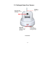
1.2 Getting to Know Your Camera Antenna for TV-IP410W only Adjustable LEDs rotate the lens to have clear image. Link LED indicates the camera’s network connectivity with the flashing green light. Power LED indicates the camera is powered on with the steady amber light.
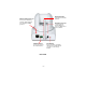
External Antenna Connects the external antenna. Ethernet Cable Connector Connecto to network by using the RJ-45 Cable. It also support the NWay protocol. DC Power Connector connects the AC power adapter, in order to supply power to the camera. GPIO Connectors It is used to connect the external device. Rear View -7- Reset Button Press it quickly to restart the camera. Press and hold for 5 seconds to set to factory default.
1.3 Features and Benefits MJPEG Supported The camera provides you with excellent MJPEG images technology, allowing you to adjust image size and quality, and bit rate according to the networking environment. Optimal Viewing With the pan/tile functions, you can easily monitor everywhere via the camera by moving the camera lens to the left/right (165/165 degrees) or up/down (90/15 degrees).
and more. The camera can capture both still images and video clips, so that you can keep the archives and restore them at any time. 1.4 System Requirement Networking LAN: 10Base-T Ethernet or 100Base-TX Fast Ethernet. WLAN: IEEE 802.11b/g. Accessing the Camera using Web Browser Platform: Microsoft® Windows® 2000/XP/Vista CPU: Intel Pentium III 800MHz or above RAM: 512MB Resolution: 800x600 or above User Interface: Microsoft® Internet Explorer 6.
C HAPTER 2 H ARDWARE I NSTALLATION 2.1 Installing the Wall Mount Kit The camera comes with a Wall Mount Kit, which allows you to place your camera anywhere by mounting the camera through the three screw holes located in the base of the Wall Mount Kit.
2.2 Connecting the Camera to LAN/WLAN Use the provided Ethernet cable to connect the camera to your local area network (LAN). When you connect the AC power adapter, the camera is powered on automatically. You can verify the power status from the Power LED on the front panel of the camera. Once connected, the Link LED starts flashing green light and the camera is on standby and ready for use now.
2.3 Applications of the Camera The camera can be applied in multiple applications, including: Monitor local and remote places and objects via Internet or Intranet. Capture still images and video clips remotely. Upload images or send email messages with the still images attached. The following diagram explains one of the typical applications for your camera and provides a basic example for installing the camera.
C HAPTER 3 A CCESSING T HE C AMERA 3.1 Using IPSetup The camera comes with a conveniently utility, IPSetup, which is included in the Installation CD-ROM, allowing you to search the camera on your network easily. 1. Insert the Installation CD-ROM into your computer’s CD-ROM drive to initiate the Auto-Run program. 2. Click the IP Setup from the Auto-Run menu screen. Then IP Setup Wizard will appear. Click “Next” when the Welcome to the IPSetup Setup Wizard appears.
3. Click “Browse” to choose the desired destination location. By default, the destination location is C:\Program Files\TRENDnet\IPSetup. Then Click “Next”.
4. Click “Next” to confirm the IPSetup software to be installed to the computer. 5. When the Installation Complete window appears, click “Finish”.
6. After installing the IPSetup utility, the application is automatically installed to your computer, and creates a folder in “ Start \Program\TRENDnet\IPSetup”. 7. Click Start > Programs > TRENDnet > IPSetup, and then click IPSetup 8. The IPSetup window will appear. The default IP setting is set to DHCP client. The camera’s IP address will be in the same subnet as your network. If you do not have a DHCP server in your network, the IP address will default to 192.168.10.30.
- Camera Display Area: It shows the connected camera(s) within the same network Double click the IP address, it will link to Camera’s Web Configuration page. - Change IP: Click this button to bring up the following window. It allows you to change the IP Address. You can select either Static IP or click DHCP. Then, enter the Administrator ID & password. By default ID/password is: admin. When complete, click “Change”.
- Search: Click this button to search the connected camera in the same network.” - Exit: Click this button to exit the program. 3.2 Accessing to the Camera 1. Open the Web browser on your computer (example showed in the User’s Guide is based on the Internet Explorer) 2. Type the Camera IP address (For example, if your DHCP server assign it as192.168.10.30) in the web browser URL and then press [Enter]. 3. You can also double click on the selected camera from IPSetup which will open IE browser.
4. When the login window appears, enter the default User name (admin) and password (admin) and press OK to access to the main screen of the camera’s Web Configuration.
NOTE If you are initially access to the camera, you will be ask to install a new plug-in for the camera. Permission request depends on the Internet security settings of your computer. Click Yes to proceed.
Camera Information – Displays the camera’s location and the current date & time. The information can be modified in the Web Configuration. Live View Image – Displays the real-time image of the connected camera. z Move your mouse to the Live View area and click on anywhere, the camera lens will then move to the position where you clicked to display it in the central part of Live View area.
Home Up Left Right Down z Auto Patrol button controls the camera to automatically scan the preset positions once. Click Stop to stop patrolling. z Click the Number button (1~8) to move the camera lens to the preset position immediately. To set up the preset positions, move the camera lens by clicking the Left/Right/Up/Down buttons to the desired position first, then select the number (1~8) from the pulldown list and click the Apply button.
3.3 Configuring the IP Address of the PC If you are failed to access to the camera, please check the IP address of your computer. When you connect the camera to your computer directly to proceed with configuration of the camera, you need to set up the IP addresses to be in the same segment for the two devices to communicate. 1. On your computer, click Start > Control Panel to open the Control Panel window. 2. Double-click Network Connection to open the Network Connection window. 3.
C HAPTER 4 C ONFIGURING T HE C AMERA 4.1 Using the Web Configuration You can access and manage the camera through the Web browser and the provided software application SecurView. This chapter describes the Web Configuration, and guides you through the configuration of the camera by using the Web browser. To configure the camera, click Setup on the main page of Web Configuration. The Web Configuration will start from the Basic page.
Enter the desired camera name and location, then click Apply. You can also configure the camera by using the Smart Wizard as describe below. 4.2 Using Smart Wizard The camera’s Smart Wizard lets you configure your camera easily and quickly. The wizard will guide you through the necessary settings with detailed instructions on each step. To start the wizard, click Smart Wizard in the left menu bar. Step 1. Camera Settings Enter desired Camera Name, Location and Admin Password.
You will need the new password to view or configure the camera later on. Step 2.
Step 3. Email Settings Enter mail server information for sending still image to email account. Step 4.
Step 5. Confirm Settings Review your setting. Click Apply to save the setting and reboot the camera. Click
4.3 Basic Setup The Basic menu contains three sub-menus that provide the system settings for the camera, such as the Camera Name, Location, Date & Time, and User management. Basic >> System Basic - Camera Name: Enter a descriptive name for the camera. - Location: Enter a descriptive name for the location used by the camera. Indication LED This item allows you to set the LED illumination as desired. There are two options: Normal and OFF.
Basic >> Date & Time - TimeZone: Select the proper time zone for the region from the pull-down menu. - Synchronize with PC: Select this option and the date & time settings of the camera will be synchronized with the connected computer. - Synchronize with NTP Server: Select this option and the time will be synchronized with the NTP Server. You need to enter the IP address of the server and select the update interval in the following two boxes. - Manual: Select this option to set the date and time manually.
Basic >> User Administrator To prevent unauthorized access to the camera’s Web Configuration, you are strongly recommend to change the default administrator password. Type the administrator password twice to set and confirm the password. General User - User Name: Enter the user’s name you want to add to use the camera. - Password: Enter the password for the new user. When you are finished, click Add/Modify to add the new user to the camera.
- UserList: Display the existing users of the camera. To delete a user, select the one you want to delete and click Delete. Guest - User Name: Enter the guest’s name you want to add to use the camera. - Password: Enter the password for the new guest. - UserList: Display the existing guests of the camera. To delete a user, select the one you want to delete and click Delete.
4.4 Network Settings The Network menu contains three sub-menus that provide the network settings for the camera, such as the IP Setting, DDNS Setting, IP Filter, and Wireless network. Network >> Network IP Setting This item allows you to select the IP address mode and set up the related configuration. The default setting is DHCP mode enabled.
- DHCP: Select this option when your network uses the DHCP server. When the camera starts up, it will be assigned an IP address from the DHCP server automatically. - Static IP: Select this option to assign the IP address for the camera directly. You can use IPSetup to obtain the related setting values. IP Enter the IP address of the camera. The default setting is DHCP. Subnet Mask Enter the Subnet Mask of the camera. The default setting is 255.255.255.0.
from the pull-down list and enter the required information in the Host Name, User Name, and Password boxes. Please note that you have to sign up for DDNS service with the service provider first. UPnP The camera supports UPnP (Universal Plug and Play), which is a set of computer network protocols that enable the device-todevice interoperability. In addition, it supports port auto mapping function so that you can access the camera if it is behind an NAT router or firewall.
Network >> IP Filter The IP Filter setting allows the administrator of the camera to limit the users within a certain range of IP addresses to access the camera. Start/End IP Address Assign a range of IP addresses that are not allowed to access the camera by entering the Start IP address and End IP address. When you are finished, click Add to save the range setting. You can repeat the action to assign multiple ranges for the camera. For example, when you enter 192.168.10.50 in Start IP Address and 192.
Deny IP List The list displays the range setting(s) of IP addresses that are not allowed to access the camera. To clear the setting, select a range of IP addresses from the list and click Delete. Network >> Wireless Setting (For TV-IP410W only) The camera supports WLAN while you use the wireless network. Select the Enable option to enable this feature. - Network ID (SSID): Keep the default setting of this option to connect the camera to any access point under the infrastructure network mode.
Ad-Hoc wireless workgroup, set the same wireless channel and SSID to match with the computer’s configuration. Click Site Survey to display the available wireless networks, so that you can easily connect to one of the listed wireless networks. - Wireless Mode: Select the type of wireless communication for the camera: Infrastructure or Ad-Hoc. - Channel: Select the appropriate channel from the list.
pair of characters you type to be interpreted as an eight-bit value in hexadecimal (base 16) notation. Key Length: Select the WEP key length you use: 64 bits or 128 bits. WEP Key 1/2/3/4: Enter the WEP key(s) in the following boxes. If you select WPA-PSK or WPA2-PSK as the Authentication mode, you need to complete the following settings: Encryption: Select TKIP or AES.
4.5 Pan/Tilt Settings The Pan/Tilt menu allows you to configure the pan/tilt functions of the camera. Pan & Tilt >> Pan & Tilt Settings - Pan/Tilt Calibration: Click Calibration to calibrate the position of the camera lens. - Pan Steps: Set the changing range (1~20 degrees) when you click the Left/Right button. - Tilt Steps: Set the changing range (1~20 degrees) when you click the Up/Down button.
4.6 Setting up Video The Video menu contains three sub-menus that provide the video settings for the camera. Video >> Camera Image Setting - Brightness: Adjust the brightness level from 0 ~ 100. - Contrast: Adjust the contrast level from 0 ~ 100. - Saturation: Adjust the colors level from 0 ~ 100. Click Default to restore the default settings of the three options above.
- Mirror: Select the Horizontal option to mirror the image horizontally. Select the Vertical option to mirror the image vertically. - Light Frequency: Select the proper frequency according to the camera’s location: 50Hz, 60Hz, or Outdoor. Overlay Setting - Includes Date & Time: Select this option to display the date & time stamp on the live view image. - Enable Opaque: Select this option to set a black background to the displayed date & time stamp.
MJPEG - Video Resolution: Select the desired video resolution from the three formats: VGA, QVGA and QQVGA. The higher setting (VGA) obtains better video quality while it uses more resource within your network. - Video Quality: Select the desired image quality from five levels: Lowest, Low, Medium, High, and Highest. - Frame Rate: Select Auto or a proper setting depending on your network status. NOTE The camera supports MJPEG compression.
4.7 Event Server Configuration The Event Server menu contains three sub-menus that allow you to upload images to FTP, send emails that include still images, and store the images to a computer. When you complete the required settings for FTP and Email, click Test to test the related configuration is correct or not. Once the camera connects to the server successfully, click Apply. Event Server Setting>> FTP - Host Address: Enter the FTP server IP address. - Port Number: Enter the FTP port number.
- Password: Enter the password to login into the FTP server. - Directory Path: Enter the destination folder for uploading the images. For example, /Test. - Passive Mode: Select the Enable option to enable passive mode. Event Server Setting >> Email - SMTP Server Address: Enter the mail server address. - Sender Email Address: Enter the email address of the user who will send the email. - Sender User Name: Enter the user name to login the mail server.
- Sender Password: Enter the password to login the mail server. - Receiver #1 Email Address: Enter the first email address of the user who will receive the email. - Receiver #2 Email Address: Enter the second email address of the user who will receive the email.
4.8 Motion Detect The Motion Detect menu contains the command and option that allow you to enable and set up the motion detection feature of the camera. The camera provides two detecting areas. To enable the detecting area, select Window 1 or 2 from the pulldown list, and then select Enable. When the detecting area is enabled, you can use the mouse to move the detecting area and change the area coverage. - Name: Assign a name to the detecting area.
4.9 Event Config The Event Config menu contains five sub-menus that provide the commands to configure event profiles. Event Configuration >> General Setting - Snapshot/Recording Subfolder: You can assign a descriptive name for the subfolder to save the captured image/video files. Otherwise, leave this option blank to use the default setting. - GPIO Trigger Out Retention Time Per Event: Limit the retention time of the GPIO Trigger Out function.
This sub-menu displays the scheduled profile(s). To customize the profile, click Add and then enter a descriptive name for the profile in the prompt dialog window. Then click OK. The profile is added to the Schedule Profiles list. To delete the profile, select the profile in the list and click Delete.
- Profile Name: Display the profile name that you select in the Schedule Profiles list. - Weekdays: Select the weekday(s) that you want to separately assign in the schedule profile. The weekday that has been assigned will be displayed with green color. - Time List: Display the time period that you have assigned within the selected weekday.
- Schedule Profile: Select a schedule profile from the pull-down list. - Action: Set the Trigger Out function or select the destination of the captured images: Send Email, or FTP Upload. NOTE Setting the Pre-event/Post-event time for sending email or uploading to FTP may cause the system overloads. Event Configuration >> Schedule Trigger You can separately configure the schedule for trigger function of the camera by Email or FTP.
and then select a Schedule Profile from the pull-down list and set the Interval time. Event Configuration >> GPIO Trigger Select the Enable option to enable the GPIO trigger function of the camera, so that you can set Trigger Out function or send captured images within the detecting area to the FTP server or email receiver,. You have to configure corresponding settings, such as FTP server and email server, to enable this feature.
- Schedule Profile: Select a schedule profile from the pull-down list. - Action: Set the Trigger Out function or select the destination of the captured images: Send Email, or FTP Upload. NOTE Setting the Pre-event/Post-event time for sending email or uploading to FTP may cause the system overloads.
4.10 Tools The Tools menu provides the commands that allow you to restart or reset the camera. You can also backup and restore your configuration, and upgrade the firmware for the camera. Factory Reset Click Reset to restore all factory default settings for the camera. System Reboot Click Reboot to restart the camera just like turning the device off and on. The camera configuration will be retained after rebooting.
You can save your camera configuration as a backup file on your computer. Whenever you want to resume the original settings, you can restore them by retrieving the backup file. - Backup: Click Get the backup file to save the current configuration of the camera. - Restore: Click Browse to locate the backup file and then click Restore. Update Firmware This item displays the current firmware version. You can upgrade the firmware for your camera once you obtained a latest version of firmware.
4.11 Information The Information menu displays the current configuration and events log of the camera. Device Info Display the Basic, Video, Network, and Wireless settings of the camera. System Log The Logs table displays the events log recorded by the system.
C HAPTER 5 S ECUR V IEW ™ S OFTWARE This Chapter describes detail instructions on operating SecurView™ software, a useful friendly application for ease of control and navigation requirement. 5.1 Installation 1. Insert the Installation CD-ROM into your computer’s CD-ROM drive to initiate the Auto-Run program. 2. Click the SecurView from the Auto-Run menu screen.
NOTE To use SecurView™, you must have Microsoft .NET Framework 2.0 installed in the computer. The setup wizard will detect it and, if the program is not installed yet, ask you to install it during the process of installing SecurView™. 3. Then SecurView Setup Wizard will appear.
4. Click “Browse” to choose the desired destination location. By default, the destination location is C:\Program Files\TRENDnet\SecurView. Then Click “Next”.
5. Click “Next” to confirm the SecurView software to be installed to the computer. 6. Click t When the Installation Complete window appears, click “Close”.
7. After installing the IPSetup utility, the application is automatically installed to your computer, and creates a folder in “ Start \Program\TRENDnet\SecurView”.
5.2 Using Installation 1. To launch the program, click Start > Program > TRENDnet > SecurView, and then click SecruView™. The main screen will appear as below. NOTE Please set the resolution to 1024x768 or above on your computer while using SecurView™; otherwise, the displayed main screen may be distorted.
- SETTING: Click to enter the Setting screen of SecurView™. Click again to return to the main screen of SecurView™. - PLAY: Click to play the recorded video file using the media player on the computer (for example, Windows Media Player by default). - LOCK: Click to lock the camera controls. Click again to resume controls for the camera. If you have set ID and Password in SETTING > Account, you will be asked to enter the required information to unlock.
- ALL RECORD: Click to start recording video clips using ALL connected cameras. To stop recording, please click Record to stop the individual camera. Please note: stop button recording only stop the manual recording camera. For schedule recording, please change the setting on configuration. TIP By default, the ID and Password boxes are “blank.” Click SETTING > Account to change the ID and password of lock/unlock function.
- NEXT: When multiple cameras connected, click this button to switch the video view to the next camera. TIP To set the time interval of scanning, click SETTING > Other and then adjust the time from 1 to 10 seconds in the Time interval of scan option. CAMERA Panel - TRIGGER OUT: Click to turn on the trigger out connector of the camera.
SYSTEM Panel This panel displays the current date and time. PAN-TILT CONTROL Panel When you connect a pan/tilt camera, the system will detect the camera’s function automatically and the PAN-TILT CONTROL buttons will become functional. Otherwise, these buttons are displayed as gray out buttons. - Direction/Home buttons: Click these buttons to adjust the camera’s viewing angle to Up ( Right ( ) / Left-Up ( Right-Down ( ) / Down ( ) / Left-Down ( ) / Left ( )/ ) / Right-Up ( )/ ).
Video View Window and Camera List Video Viewing Window Camera List - Video Viewing Window: This window displays the video view of the selected camera, which can be divided into 4/9/16 windows according to your selection in VIEW SELECTION panel. - Camera List: This list displays the information of the connected camera(s).
To add a camera 1. Click SETTING in the CONTROLS panel to display the Setting screen. 2. Click Add New Camera.
3. In the pop-up Add New Camera dialog window, you can: z Select the Search tab if you are not sure of the camera’s IP address. Click Search camera to search the available camera within the network. Once the camera is found and is shown in the list, select it and click Add Camera. z Select the Input tab to add a camera by entering its IP address directly. Enter the camera’s IP address and Port default: 80), and then click Add Camera.
4. Enter the User name and Password for the camera, and then click OK. The connected camera will be displayed in the Camera List.
5. Click SETTING to return to the Video View Window. The video view of the selected camera will be displayed now. To remove a camera 1. Click SETTING in the CONTROLS panel to display the Setting screen. 2. Select a camera from the list and click Delete Camera.
Select a camera Delete the camera To link to the Web page of the camera Click SETTING > Camera List > Camera Configuration and then Link web page to launch the Web browser that displays live view image and Web Configuration of the selected camera.
To record video SecurView™ provides three methods to record video clips: one is to click the RECORD/All Record button to record manually; the second is to record by motion detection; the third is to set the recording schedule in Setting > Recording Configuration > Schedule Recording Configuration. z Manually recording Click RECORD/All Record and it starts recording. Click the button again to stop.
z Trigger recording by motion detection When the motion detection function of the selected camera is enabled, you can configure the camera to start recording triggered by the motion detected. Click SETTING > Motion Configuration, and then select the Recording option to enable the selected camera to record by motion detection.
z Schedule recording Configuration This recording method will work after you have completed the required settings in Schedule Recording Configuration. The recording schedule can be defined by Dates or Days. - Dates: Select the camera from the pull-down list.. Select a camera Add Schedule - Then, click Add to set the Start/Stop date and time and then click OK to add the recording schedule to the list.
- Click Apply to save the settings - 76 -
Days: First, select the camera from the pull-down list and select Days tab. Then, select the weekday from the day buttons and then set the time period. Click Apply to save the settings. To configure the recording settings To configure the recording settings, including the storage folder and storage options, click SETTING > Recording Configuration.
z Recording File Path: To change the destination folder to save the recorded video file, click Browse under the Recording File Path box to assign a new folder. z Each Recording File Size: This option allows you to select from 20 to 100 MB so that the video will be recorded as another file automatically when the recording file reaches the specified size limit.
space on the hard disk drive, you can check the available storage space that is displayed in the HDD Free space field. z Enable Recycle Recording: Click on the camera number to clear the files when the unreserved space of the hard disk drive is full. To playback the recorded video The recorded video clips are saved in your computer, and can be played using the media player on the computer, such as Windows Media Player.
NOTE If your player on the computer don’t have video codec to playback the recorded video. You can download video codec from http://www.xvid.org/downloads.15.0.html to support. To set up motion detection options When the motion detection function of the selected camera is enabled, you can set the Motion Options by selecting Alarm, Recording, Send e-Mail, and Trigger Out under SETTING > Motion Configuration.
z Alarm: Select Beep or Music to alert you for the motion detected. When you select Music, you can customize the sound by clicking Browse and then selecting your favorite music (*.wav or *.mp3 file) in the computer. z Recording: Select this option to enable the camera to record by motion detected. z Send Email: Select this option so that the system will be able to send an email to the specified receiver.
- Mail From: Enter the email address of the user who will send the email. For example, John@mymail.com. - Mail To: Enter the email address of the user who will receive the email. - User Name: Enter the user name to login the mail server. - Password: Enter the password to login the mail server. - Subject: Enter a subject for the notification email. z Trigger Out: If the selected camera supports Trigger Out connector, select this option to enable the Trigger Out function.
Information Click SETTING > About to display the information of the software application.
- 84 -
A PPENDIX A.1 Specification Image Sensor Sensor Resolution 1/4” color CMOS 640x480 Video Compression Video resolution MJPEG VGA/QVGA/QQVGA; 30fps max.
LAN WLAN 10/100Mbps Fast Ethernet, auto-sensed, Auto-MDIX IEEE 802.11b/g Protocol support TCP/IP, UDP, ICMP, DHCP, NTP, DNS, DDNS, SMTP, FTP, PPPoE, UPnP Pan/Tilt Pan Tilt 165 degree (left) to 165 degree (right) 90 degree (up) to 15 degree (down) Software OS Support Browser Windows 2000/XP/Vista Internet Explorer 6.
A.2 GPIO Terminal Application Typically used in association with programming scripts for developing applications for motion detection, event triggering, alarm notification via e-mail, and a variety of external control functions. The GPIO connectors are located on the rear panel of the camera, which provide the interface of connecting the sensor device (IN) and controlled device (OUT).
A.3 Glossary of Terms NUMBERS 10BASE-T 100BASE-TX 10BASE-T is Ethernet over UTP Category III, IV, or V unshielded twisted-pair media. The two-pair twisted-media implementation of 100BASET is called 100BASE-TX. A ADPCM Applet ASCII ARP AVI Adaptive Differential Pulse Code Modulation, a new technology improved from PCM, which encodes analog sounds to digital form. Applets are small Java programs that can be embedded in an HTML page.
Connection message, and medium. In networks, devices and application tasks and processes communicate messages to each other over media. They represent the sender and receivers. The data they send is the message. The cabling or transmission method they use is the medium. In networking, two devices establish a connection to communicate with each other. D DHCP DNS Developed by Microsoft, DHCP (Dynamic Host Configuration Protocol) is a protocol for assigning dynamic IP addresses to devices on a network.
network Ethernet area. The enterprise network serves the needs of a widely distributed company and operates the company’s mission-critical applications. The most popular LAN communication technology. There are a variety of types of Ethernet, including 10Mbps (traditional Ethernet), 100Mbps (Fast Ethernet), and 1,000Mbps (Gigabit Ethernet). Most Ethernet networks use Category 5 cabling to carry information, in the form of electrical signals, between devices.
system, which consists of 16 unique symbols: the numbers 0 to 9 and the letters A to F. For example, the decimal number 15 is represented as F in the hexadecimal numbering system. The hexadecimal system is useful because it can represent every byte (8 bits) as two consecutive hexadecimal digits. It is easier for humans to read hexadecimal numbers than binary numbers. I Intranet This is a private network, inside an organization or company that uses the same software you will find on the public Internet.
ISP ISP (Internet Service Provider) is a company that maintains a network that is linked to the Internet by way of a dedicated communication line. An ISP offers the use of its dedicated communication lines to companies or individuals who can’t afford the high monthly cost for a direct connection. J JAVA Java is a programming language that is specially designed for writing programs that can be safely downloaded to your computer through the Internet without the fear of viruses.
Network NWay Protocol problem. When devices within your network request information from the Internet, the requests are forwarded to the Internet under the router's IP address. NAT distributes the responses to the proper IP addresses within your network. A network consists of a collection of two or more devices, people, or components that communicate with each other over physical or virtual media.
responsible for formatting and presenting and presenting data that will be transferred from file server memory to the file server’s net work adapter Others are responsible for filtering information between networks and forwarding data to its destination. Still other protocols dictate how data is transferred across the medium, and how servers respond to workstation requests and vice versa.
Station Subnet mask In LANs, a station consists of a device that can communicate data on the network. In FDDI, a station includes both physical nodes and addressable logical devices. Workstations, single-attach stations, dual-attach stations, and concentrators are FDDI stations. In TCP/IP, the bits used to create the subnet are called the subnet mask.
WAN WEP Windows WPA WPA2 Wide-Area Network. A wide-area network consists of groups of interconnected computers that are separated by a wide distance and communicate with each other via common carrier telecommunication techniques. WEP is widely used as the basic security protocol in WiFi networks, which secures data transmissions using 64bit or 128-bit encryption. Windows is a graphical user interface for workstations that use DOS.
Limited Warranty TRENDnet warrants its products against defects in material and workmanship, under normal use and service, for the following lengths of time from the date of purchase.
TRENDNET SHALL NOT BE LIABLE UNDER THIS WARRANTY IF ITS TESTING AND EXAMINATION DISCLOSE THAT THE ALLEGED DEFECT IN THE PRODUCT DOES NOT EXIST OR WAS CAUSED BY CUSTOMER’S OR ANY THIRD PERSON’S MISUSE, NEGLECT, IMPROPER INSTALLATION OR TESTING, UNAUTHORIZED ATTEMPTS TO REPAIR OR MODIFY, OR ANY OTHER CAUSE BEYOND THE RANGE OF THE INTENDED USE, OR BY ACCIDENT, FIRE, LIGHTNING, OR OTHER HAZARD.
- 99 -