P REFACE Thank you for purchasing the TV-IP252 SecurView PoE Dome Internet Camera, a standalone system that can be connected directly to an Ethernet or Fast Ethernet network. The camera features the latest Motion JPEG and MPEG-4 image technology, advanced management functionality, and GPIO connectors (e.g.
This User Guide provides you with the instructions and illustrations on how to use your camera, which includes: Chapter 1 Introduction to Your Camera describes the features of the camera. You will also know the components and functions of the camera. Chapter 2 Hardware Installation helps you install the camera according to your application environment. You can use this camera at home, at work, any where you want. Chapter 3 Accessing the Camera lets you start using your camera without any problems.
Contents PREFACE ......................................................................... 1 CHAPTER 1 ..................................................................... 5 INTRODUCTION TO YOUR CAMERA ....................... 5 1.1 1.2 1.3 1.4 CHECKING THE PACKAGE CONTENTS ................................... 5 GETTING TO KNOW YOUR CAMERA ..................................... 6 FEATURES AND BENEFITS ..................................................... 9 SYSTEM REQUIREMENT .................................
A.1 SPECIFICATION .................................................................... 90 A.2 GLOSSARY OF TERMS .........................................................
C HAPTER 1 I NTRODUCTION T O Y OUR C AMERA 1.1 Checking the Package Contents Check the items contained in the package carefully. You should have the following: TV-IP252P Power Adapter (12V DC, 1.5A) Mounting Kit Cat. 5 Ethernet Cable (1.8m / 6ft.) GPIO Adapter CD-ROM (Utility & User’s Guide) Multi-Language Quick Installation Guide NOTE If there is any item damaged or missing, please contact your local authorized dealer for replacement.
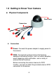
1.2 Getting to Know Your Camera Physical Components Dome cover Connectors Connectors Power: Connects the power adapter to supply power to the camera. GPIO: Connects the external device that features additional controlling function, such as motion detection, event triggering, alarm notification, and a variety of external control functions. Before connecting the external device for GPIO function, you have to attach the provided external GPIO connectors to the device.
Mic In: Connects an external microphone to receive the on-the-spot sound where the camera is installed. (Pink Connector) Audio Out: Connects an external audio device (such as the active speaker) to deliver sound via the camera. (Green Connector) TV Out: The BNC connector is used to connect the composite video input of external video device. LAN: Plugs the provided Ethernet cable to connect to your local area network (LAN).
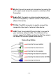
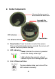
Inside Components Unscrew the four screws to disassemble the Dome cover. Lens with the adjustable base LED indicators Reset button Link & Power switches Reset button: Press the button to restart the camera. Press and hold the button for five seconds, the camera will resume the factory default settings. LED indicators - Power indicates the camera is powered on with the steady amber light. - Link indicates the camera’s network connectivity with the flashing green light.
1.3 Features and Benefits MPEG4/MJPEG Dual-codec Supported The camera provides you with excellent images by the MPEG4/MJPEG dual-codec selectable technology, allowing you to adjust image size and quality, and bit rate according to the networking environment. Flexible Audio Capability The camera allows you to connect the external microphone to receive on-the-spot audio via the Internet, allowing you to monitor the on-site voice.
I/O Connectors Supported The I/O connectors (2-in/1-out) of the camera provide the physical interface to send and receive digital signals to a variety of external alarm devices. You can configure the settings and control the device from the GPIO Trigger setting of Web Configuration. Multiple Platforms Supported The camera supports multiple network protocols, including TCP/IP, SMTP e-mail, HTTP, and other Internet related protocols.
1.4 System Requirement Networking - LAN: 10Base-T Ethernet or 100Base-TX Fast Ethernet. Accessing the Camera using SecurView™ - Platform: Microsoft® Windows® 2000/XP/Vista. Accessing the Camera using Web Browser - Platform: Microsoft® Windows® 2000/XP/Vista - CPU: Intel Pentium III 350MHz or above - RAM: 128MB - Resolution: 800x600 or above - User Interface: Microsoft® Internet Explorer 6.
C HAPTER 2 H ARDWARE I NSTALLATION 2.1 Applications of the Camera The camera can be applied in multiple applications, including: Monitor local and remote places and objects via Internet or Intranet. Capture still images and video clips remotely. Upload images or send email messages with the still images attached. The following diagram explains one of the typical applications for your cameras and provides a basic example for installing the cameras.
2.2 Installing the Camera Basic Installation (Surface) The camera can be mounted to the ceiling surface directly by the following steps: 1. Remove the Dome cover by unscrewing four screws. 2. Drill three pilot holes into the ceiling and hammer the plastic anchors into the holes. TIP You can easily and precisely drill the three pilot holes with the provided drill template.
3. Install the camera to the ceiling with three screws.
4. Make connections according to your needs (refer to the illustration of connecting cables on page 6). 5. Pan/tilt the camera lens to a proper position by using the adjustable base, and adjust the lens focus by turning the lens ring slowly in either clockwise or anti-clockwise direction. NOTE You can review the image quality from the Web browser when you complete the installation.
- 16 -
C HAPTER 3 A CCESSING T HE C AMERA 3.1 Using IPSetup The camera comes with a convenient utility, IPSetup, which is included in the Installation CD-ROM, allowing you to search the camera(s) on your network easily. 1. Insert the Installation CD-ROM into your computer’s CDROM drive to initiate the Auto-Run program. 2. Click the IPSetup from the Auto-run menu screen. Then the IPSetup Wizard will appear. Click Next when the Welcome to the IPSetup Wizard appears.
3. Click Browse to choose the desired destination location. By default the destination location is C:\Program Files\TRENDnet\IPSetup. Then click Next.
4. Click Next to confirm the IPSetup software to be installed to the computer. 5. When the Installation Complete window appears, click Close.
6. After installing the IPSetup Utility, the application is automatically installed to your computer, and creates a folder in Start\Program\TRENDnet\IPSetup. 7. Click Start>Programs>TRENDnet>IPSetup, and then click IPSetup. 8. The IPSetup window will appear.
Camera Display Area: It shows the connected camera(s) within the same network. Double click the IP Address, it will link to the Camera’s Web Configuration page. - Change IP: Click this button to bring up the following window. It allows you to change the IP Address. You can select either Static IP or click DHCP. Then, enter the Administrator ID & Password. By default the ID/Password is: admin. When complete, click Change.
3.2 Accessing to the Camera Whenever you want to access the camera: 1. Open the Web browser on your computer (example showed in the User’s Guide is based on Internet Explorer). 2. Since the default configuration of the camera is DHCP mode enabled, you are recommended to launch IPSetup to search the IP address that is assigned to the camera by the DHCP server, and then click Link to access the camera via the Web browser. Otherwise type the default IP address (192.168.10.
NOTE If you are initially accessing the camera, you will be asked to install a new plug-in for the camera. Permission request depends on the Internet security settings of your computer. Click Yes to proceed.
Compression Buttons: Select to transmit and record the video using MPEG4 or MJPEG compression. Function Buttons: Use these buttons to control the audio, video, and trigger functions. Manual Record allows you to record and save a video clip. Snapshot allows you to capture and save a still image. Browse allows you to assign the destination folder to store the video clips and still images. Talk allows you to speak out through the camera.
2. Click Tools > Internet Options. 3. Click Security. 4. Disable the Enable Protected Mode option and then click OK.
3.3 Configuring the IP Address of the PC If you have failed to access the camera, please check the IP address of your computer. When you connect the camera to your computer directly, proceed with configuration of the camera. You need to set up the IP addresses to be in the same segment for the two devices to communicate. 1. On your computer, click Start > Control Panel to open the Control Panel window. 2. Double-click Network Connection to open the Network Connection window. 3.
C HAPTER 4 C ONFIGURING THE C AMERA 4.1 Using the Web Configuration You can access and manage the camera through the Web browser and the provided software application SecurView™ (see chapter 5 in more detail). This chapter describes the Web Configuration, and guides you through the configuration of the camera by using the web browser. To configure the camera, click Setup on the Main page of Web Configuration. The Web Configuration will start from the Basic page.
The Web Configuration contains the settings that are required for the camera in the left menu bar, including Smart Wizard, Basic, Network, Video/Audio, Event Server, Motion detect, Event Config, Tools, USB, and Information. 4.2 Using Smart Wizard The camera’s Smart Wizard lets you configure your camera quickly and easily. The wizard will guide you through the necessary settings with detailed instructions on each step. To start the wizard, click Smart Wizard in the left menu bar. Step 1.
Step 3. Email Settings Enter the required information to be able to send email with image.
Step 4. Confirm Settings The last step shows the configuration of your camera. When you confirm the settings, click Apply to finish the wizard and reboot the camera. Otherwise, click Prev to go back to the previous step(s) and change the settings; or click Cancel to end the wizard and discard the changes.
4.3 Basic Setup The Basic menu contains three sub-menus that provide the System settings for the camera, such as the Camera Name, Location, Date & Time, and User management.
Basic: This item allows you to assign the camera name and location information. - Camera Name: Enter a descriptive name for the camera. - Location: Enter a descriptive name for the location where the camera is monitored. Indication LED: This item allows you to set the LED illumination as desired. There are two options: Normal and OFF. Basic >> Date & Time Date & Time: Enter the correct date and time for the system. - TimeZone: Select the proper time zone for the region from the pull-down menu.
- Synchronize with PC: Select this option and the date & time settings of the camera will be synchronized with the connected computer. - Synchronize with NTP Server: Select this option and the time will be synchronized with the NTP Server. You need to enter the IP address of the server and select the update interval in the following two boxes. - Manual: Select this option to set the Date and Time manually.
password. Type the administrator password twice to set and confirm the password. General User - User Name: Enter the user’s name you want to add to use the camera. - Password: Enter the password for the new user. When you are finished, click Add/Modify to add the new user to the camera. To modify the user’s information, select the one you want to modify from UserList and click Add/Modify. - UserList: Display the existing users of the camera.
embedding the video stream into a custom application or webpage. Examples of the Direct Link to video: MPEG4 Mode http://camera_ip_address:port number/mpgview.htm MJPEG Mode http://camera_ip_address:port number/jpgview.htm NOTE The “General User” is allowed to access the camera and control the Function buttons on the Main screen of the Web Configuration. The “Guest” can only view the live view image from the Main screen while accessing the camera.
Network >> Network - 36 -
IP Setting: This item allows you to select the IP address mode and set up the related configuration. - DHCP: Select this option when your network uses the DHCP server. When the camera starts up, it will be assigned an IP address from the DHCP server automatically.
- Static IP: Select this option to assign the IP address for the camera directly. You can use IPSetup to obtain the related setting values. IP Enter the IP address of the camera. The default setting is 192.168.10.30. Subnet Mask Enter the Subnet Mask of the camera. The default setting is 255.255.255.0. Default Gateway Enter the Default Gateway of the camera. The default setting is 192.168.10.1. Primary/ Secondary DNS DNS (Domain Name System) translates domain names into IP addresses.
NOTE You have to sign up for DDNS service with the service provider before configuring this feature. UPnP: The camera supports UPnP (Universal Plug and Play), which is a set of computer network protocols that enable the device-to-device interoperability. In addition, it supports port auto mapping function so that you can access the camera if it is behind an NAT router or firewall. Select the Enable option to enable this feature. Ports Number - HTTP Port: The default HTTP port is 80.
The IP Filter setting allows the administrator to limit the users within a certain range of IP addresses to have access to the camera. To disable this feature, select the Disable option; otherwise, select the Accept option to assign the range of IP addresses that are allowed to access the camera, or select the Deny option to assign the range of IP addresses that are blocked to access the camera.
For example, when you enter 192.168.10.50 in Start IP Address and 192.168.10.80 in End IP Address, the user whose IP address located within 192.168.10.50 ~ 192.168.10.80 will not be allowed to access the camera. - Accept IP List: The list displays the range setting(s) of IP addresses that are allowed to access the camera. To clear the setting, select a range of IP addresses from the list and click Delete.
4.5 Setting up Video & Audio The Video & Audio menu contains four sub-menus that provide the video and audio settings for the camera.
Image Setting - Brightness: Adjust the brightness level from 0 ~ 100. - Saturation: Adjust the colors level from 0 ~ 100. - Sharpness: Adjust the sharpness level from 0 ~ 100. Click Default to restore the default settings of the three options above. - Mirror: Select Vertical to mirror the image vertically, or select Horizontal to mirror the image horizontally. - Light Frequency: Select the proper frequency according to the camera’s location: 50Hz or 60Hz.
MPEG4 - Video Resolution: Select the desired video resolution from the three formats: VGA, QVGA, and QQVGA. The higher setting (VGA) obtains better video quality while it uses more resource within your network. - Video Quality: Select the desired image quality from five levels: Lowest, Low, Medium, High, and Highest. - Frame Rate: Select Auto or a proper setting depending on your network status. MJPEG - Video Resolution: Select the desired video resolution from the three formats: VGA, QVGA, and QQVGA.
3GPP: The camera supports 3GPP specification. To disable this feature, select the Disable option; otherwise, select 3GPP Without Audio or 3GPP With Audio to transfer the video clips without or with audio. If you use a mobile phone that supports 3GPP, you can also view the real-time streaming image captured by the camera on your phone (with the default player on the phone) by entering the RTSP link: rtsp://(IP address of the camera)/3gp.
Overlay Setting: This option allows you to set the overlay function of the camera, so that you can see the related information on the live view image. - Includes Date & Time: Select this option to display the date & time stamp on the live view image. - Include Text: Select this option and enter your heading text in the box to display the text information on the live view image. - Enable Opaque: Select this option to set a black background to the displayed date & time stamp.
4.6 Event Server Configuration The Event Server menu contains three sub-menus that allow you to upload images to FTP, send Emails that include still images, and store the images to a NAS system. When you complete the required settings for FTP, Email, or Network Storage, click Test to test the related configuration is correct or not. Once the camera connects to the server successfully, click Apply.
FTP - Host Address: Enter the IP address of the target FTP server. - Port Number: Enter the port number used for the FTP server. - User Name: Enter the user name to login into the FTP server. - Password: Enter the password to login into the FTP server. - Directory Path: Enter the destination folder for uploading the images. For example, /Test/. - Passive Mode: Select the Enable option to enable passive mode. - FTP Upload With: Set the format of the image that is to be uploaded to the FTP server.
format as One Snapshot or images containing Preevent (0 ~ 3) seconds and Post-event (0 ~ 3) seconds. Event Server Setting >> Email Email - SMTP Server Address: Enter the mail server address. For example, mymail.com. - Sender Email Address: Enter the email address of the user who will send the email. For example, John@mymail.com.
the User Name and Password according to the mail server configuration. - Sender User Name: Enter the user name to login the mail server. - Sender Password: Enter the password to login the mail server. - Receiver #1 Email Address: Enter the first email address of the user who will receive the email. - Receiver #2 Email Address: Enter the second email address of the user who will receive the email. - Send Email With: Set the format of the image that is to be sent by the email.
Network Storage - Samba Server Address: Enter the IP address of the Network Storage server. - Share: Assign the folder on the Network Storage server to share the files to users. - Path: Assign the path for uploading the files on the Network Storage server. For example, /Test/. - User Name: Enter the user name to login into the Network Storage server. - Password: Enter the password to login into the Network Storage server.
4.7 Motion Detect The Motion Detect menu contains the command and option that allow you to enable and set up the motion detection feature of the camera. The camera provides two detecting areas. To enable the detecting area, select Window 1 or 2 from the pulldown list, and then select Enable. When the detecting area is enabled, you can use the mouse to move the detecting area and change the area coverage. Name: Assign a name to the detecting area.
4.8 Event Config The Event Config menu contains five sub-menus that provide the commands to configure event profiles. Event Configuration >> General Setting General - Snapshot/Recording Subfolder: You can assign a given subfolder to each new captured file. Otherwise, leave this option blank to use the default setting. - Network Storage Recording Time Per Event: Limit the recording time while you are using the Network Storage solution.
- GPIO Trigger Out Retention Time Per Event: Limit the retention time of the GPIO Trigger Out function. Event Configuration >> Arrange Schedule Profile Schedule Profile: This sub-menu displays the scheduled profile(s). To customize the profile, click Add and then enter a descriptive name for the profile in the prompt dialog window. After entering the profile name, click OK and the profile is added to the Schedule Profiles list. To delete the profile, select the profile in the list and click Delete.
- Profile Name: Display the profile name that you select in the Schedule Profiles list. - Weekdays: Select the weekday(s) that you want to separately assign in the schedule profile. The weekday that has been assigned will be displayed with green color. - Time List: Display the time period that you have assigned within the selected weekday.
captured images within the detecting area to the FTP server, email receiver, Network Storage server, or the connected USB device. You have to configure corresponding settings, such as FTP server and email server, to enable this feature. Please note that you have to configure the related settings before enabling these features. - Schedule Profile: Select a schedule profile from the pull-down list.
the Enable option on each item, and then select a Schedule Profile from the pull-down list and set the Interval time. NOTE If the setting value of the Network Storage Recording Time Per Event option in General Setting is longer than the Interval time in Network Storage Schedule, the recorded file will be a continuous video clip.
detecting area to the Network Storage server, email receiver, or FTP server. You have to configure corresponding settings, such as FTP server and email server, to enable this feature. Enable Trigger In 1/2: Select the option to enable the GPIO trigger function of the camera. Then, complete the following options - Schedule Profile: Select a schedule profile (Always, or the profile you have set) from the pull-down list.
4.9 Tools The Tools menu provides the commands that allow you to restart or reset the camera. You can also backup and restore your configuration, and upgrade the firmware for the camera. Factory Reset: Click Reset to restore all factory default settings for the camera. System Reboot: Click Reboot to restart the camera just like turning the device off and on. The configuration of the camera will be retained after rebooting.
resume the original settings, you can restore them by retrieving the backup file. - Backup: Click Get the backup file to save the current configuration of the camera. - Restore: Click Browse to locate the backup file and then click Restore. Update Firmware: You can upgrade the firmware for your camera once you obtained a latest version of firmware. - Current Firmware Version: This item displays the current firmware version.
4.10 Information The Information menu displays the current configuration and events log of the camera. Information >> Device Info Display the Basic, Video & Audio, and Network settings of the camera.
The Logs table displays the events log recorded by the system.
C HAPTER 5 SECURVIEW™ SOFTWARE This chapter describes detailed instructions on operating SecurView™ software, a useful friendly application for ease of control and navigation requirement. 5.1 Installation 1. Insert the Installation CD-ROM into your computer’s CDROM drive to initiate the Auto-Run program. 2.
NOTE To use SecurView™, you must have Microsoft .NET Framework 2.0 installed in the computer. The setup wizard will detect it and, if the program is not installed yet, ask you to install it during the process of installing SecurView™. 3. Then SecurView Setup Wizard will appear. Click Next when the Welcome to the SecurView Setup Wizard appears.
4. Click Browse to choose the desired destination location. By default, the destination location is C:\Program Files\TRENDnet\SecurView. Then click Next.
5.
6. When the Installation Complete window appears, click Close. 7. After installing the IPSetup utility, the application is automatically installed to your computer, and creates a folder in Start\Program\TRENDnet\SecurView.
5.2 Using Installation 1. To launch the program, click Start>Program>TRENDnet>SecurView, and then click SecurView™. The main screen will appear as below. NOTE Please set the resolution to 1024 x 768 or above on your computer while using SecurView™; otherwise, the displayed main screen may be distorted.
Item Features The following describes the function of each item on the main screen: CONTROLS Panel - SETTING: Click to enter the Setting screen of SecurView™. - Click again to return to the main screen of SecurView™. - Play: Click to play the recorded video file using the media player on the computer (for example, Windows Media Player by default).
- Lock: Click to lock the camera controls. Click again to resume controls for the camera. If you have set ID and Password in Setting>Account, you will be asked to enter the required information to unlock. - ALL RECORD: Click to start recording video clips using ALL connected cameras. To stop recording, please click Record button to stop the individual camera. Please note: stop recording only stops the manual recording camera. For Schedule recording, please change the setting on configuration.
- Scan: When multiple cameras connected, click this button to display the video views between cameras. Click the Scan button again to stop scanning. - PREV: When multiple cameras connected, click this button to switch the video view to the previous camera. - NEXT: When multiple cameras connected, click this button to switch the video view to the next camera.
- RECORD: Click to start recording a video clip using the selected camera. Click again to stop recording and save the file in the computer. - TALK: Click to speak out through the camera. Please note only one user is allowed to use this function at the same time. - LISTEN: Click to receive the on-site sound and voice from the camera. SYSTEM Panel This panel displays the current date and time.
- Video Viewing Window: This window displays the video view of the selected camera, which can be divided into 4/9/16 windows according to your selection in VIEW SELECTION panel. - Camera List: This list displays the information of the connected camera(s). To add a camera 1. Click SETTING in the CONTROLS panel to display the Setting screen. 2. Click Add New Camera.
3. In the pop-up Add New Camera dialog window, you can: Select the Search tab if you are not sure of the camera’s IP Address. Click Search camera to search for an available camera within the network. Once the camera is found and is shown in the list, select it and click Add Camera. Select the Input tab to add a camera by entering its IP Address directly. Enter the camera’s IP Address (default: 192.168.10.30) and Port (default: 80), and then click Add Camera.
4. Enter the User name and Password for the camera, and then click OK. The connected camera will be displayed in the Camera’s List. 5. Click SETTING to return to the Video View Window. The video view of the selected camera will be displayed now.
To remove a camera 1. Click SETTING in the CONTROLS panel to display the Setting screen. 2. Select a camera from the list and click Delete Camera.
Select a camera Delete a camera To link to the Web page of the camera Click SETTING>Camera List>Camera Configuration and then Link web page to launch the Web browser that displays live view image and Web Configuration of the selected camera.
To Record Video SecurView™ provides three methods to record video clips: one is to click the RECORD/All Record button to record manually; the second is to record by motion detection; the third is to set the recording schedule in Setting>Recording Configuration>Schedule Recording Configuration. Manually record Click RECORD/All record and it starts recording.
Trigger recording by motion detection When the motion detection function of the selected camera is enabled, you can configure the camera to start recording triggered by the motion detected. Click SETTING>Motion Configuration, and then select the Recording option to enable the selected camera to record by motion detection.
Schedule Recording Configuration This recording method will work after you have completed the required settings in the Schedule Recording Configuration. The recording schedule can be defined by Dates or Days. - Dates: Select the camera from the pull-down list.
Select a camera Add Schedule - Then, click Add to set the Start/Stop date and time and then click OK to add the recording schedule to the list.
- Click Apply to save the settings. Days: First, select the camera from the pull-down list and select Days tab. Then, select the weekday from the day buttons and then set the time period. Click Apply to save the settings.
To configure the recording settings To configure the recording settings, including the storage folder and storage options, click SETTING>Recording Configuration.
Recording File Path: To change the destination folder to save the recorded video file, click Browse under the Recording File Path box to assign a new folder. Each Recording File Size: This option allows you to select from 20 to 100 MB so that the video will be recorded as another file automatically when the recording file reaches the specified size limit.
Enable Recycle Recording: Click on the camera number to clear the files when the unreserved space of the hard disk drive is full. To playback the recorded video The recorded video clips are saved in your computer, and can be played using the media player on the computer, such as Windows Media Player. To start playback, simply click the PLAY button on the CONTROLS panel, and the following dialog screen will appear, allowing you to select the file to playback.
the video code from http://www.xvid.org/downloads.15.0.html to support. To set up motion detection options When the motion detection function of the selected camera is enabled, you can set the Motion Options by selecting Alarm, Recording, Send e-Mail, and Trigger Out under SETTING> Motion Configuration. Alarm: Select Beep or Music to alert you for the motion detected. When you select Music, you can customize the sound by clicking Browse and then selecting your favorite music (*.wav or *.
Recording: Select this option to enable the camera to record by motion detected. Send Email: Select this option so that the system will be able to send an email to the specified receiver. Once the option is selected, you have to complete the required information in SETTING>Motion Configuration>Email Configuration. - Mail Server: Enter the mail server address. For example, mymail.com. Mail From: Enter the email address of the user who will send the email. For example, John@mymail.com.
- Password: Enter the password to login the mail server. - Subject: Enter a subject for the notification email. Trigger Out: If the selected camera supports Trigger Out connector, select this option to enable the Trigger out function. Account Click SETTING>Account to setup the username & password to lock & unlock the main screen of the SecurView. Other Click SETTING>Other to setup the scanning time between cameras. The default setting is 2 seconds. You can set the interval time between 2 ~ 20 seconds.
Information Click SETTING>About to display the information of the software application.
C HAPTER 6 APPENDIX A.1 Specification System Hardware - Processor - RAM - ROM - Power Image Sensor - Sensor ARM9 base 32MB SDRAM 8MB NOR Flash DC 12V - Resolution 1/4” Low Lux CMOS sensor; minimum illumination @ 0.1 LUX 640 x 480 Lens Assembly - Lens Type - Aperture (F/No.) - Focus Length - View Angle Board Lens 2.0 4.2 mm (Diagonal) 60 degree Video - Compression - Exposure Control - White Balance - Gain control - Video Resolution MPEG4/MJPEG Auto Auto Auto VGA/QVGA/QQVGA; 30 fps max.
- Protocol User Interface - LAN - Reset - GPIO - TV Out - Switches - LEDs Audio - Input - Output - Codec Software - OS Support - Browser - Software TCP/IP, UDP, ICMP, DHCP, NTP, DNS, DDNS, SMTP, FTP, HTTP, Samba, PPPoE, UPnP, Bonjour, RTP, RTSP, RTCP One RJ-45 port One Reset button 2 in / 1 out BNC connecter, 1 Vp-p, 75 Ohms One Power LED switch; one Link LED switch One Power LED (amber); one Link LED (green) External microphone jack Headphone output jack (Mono) PCM/AMR (AMR is for 3GPP only)
A.2 Glossary of Terms Typically used in association with programming scripts for developing applications for motion detection, event triggering, alarm notification via e-mail, and a variety of external control functions. The 6-pin I/O Terminal Block is located on the rear panel and provides the interface to: a photo-coupled switch output, a photo-coupled input.
- 93 -
A.3 Glossary of Terms NUMBERS 10BASE-T 100BASE-TX 10BASE-T is Ethernet over UTP Category III, IV, or V unshielded twisted-pair media. The two-pair twisted-media implementation of 100BASE-T is called 100BASE-TX. A ADPCM Adaptive Differential Pulse Code Modulation, a new technology improved from PCM, which encodes analog sounds to digital form. AMR AMR (Adaptive Multi-Rate) is an audio data compression scheme optimized for speech coding, which is adopted as the standard speech codec by 3GPP.
B BOOTP Bootstrap Protocol is an Internet protocol that can automatically configure a network device in a diskless workstation to give its own IP address. C Communication Communication has four components: sender, receiver, message, and medium. In networks, devices and application tasks and processes communicate messages to each other over media. They represent the sender and receivers. The data they send is the message. The cabling or transmission method they use is the medium.
remember. The Internet however, is really based on IP addresses every time you use a domain name the DNS will translate the name into the corresponding IP address. For example, the domain name www.network_camera.com might translate to 192.167.222.8. E Enterprise network An enterprise network consists of collections of networks connected to each other over a geographically dispersed area.
G Gateway A gateway links computers that use different data formats together. Group Groups consist of several user machines that have similar characteristics such as being in the same department. H HEX Short for hexadecimal refers to the base-16 number system, which consists of 16 unique symbols: the numbers 0 to 9 and the letters A to F. For example, the decimal number 15 is represented as F in the hexadecimal numbering system.
network must conform to IP addressing rules. In smaller LANs, most people will allow the DHCP function of a router or gateway to assign the IP addresses on internal networks. IP address IP address is a 32-binary digit number that identifies each sender or receiver of information that is sent in packets across the Internet. For example 80.80.80.69 is an IP address. When you “call” that number, using any connection methods, you get connected to the computer that “owns” that IP address.
M MJPEG MPEG4 MJPEG (Motion JPEG) composes a moving image by storing each frame of a moving picture sequence in JPEG compression, and then decompressing and displaying each frame at rapid speed to show the moving picture. MPEG4 is designed to enable transmission and reception of high-quality audio and video over the Internet and next-generation mobile telephones.
P PCM PCM (Pulse Code Modulation) is a technique for converting analog audio signals into digital form for transmission. PING Packet Internet Groper, a utility used to determine whether a specific IP address is accessible. It functions by sending a packet to the specified address and waits for a reply. It is primarily used to troubleshoot Internet connections. PPPoE Point-to-Point Protocol over Ethernet.
R RJ-45 RJ-45 connector is used for Ethernet cable connections. Router A router is the network software or hardware entity charged with routing packets between networks. RTP RTP (Real-time Transport Protocol) is a data transfer protocol defined to deliver live media to the clients at the same time, which defines the transmission of video and audio files in real time for Internet applications.
T (TCP/IP) Transceiver Transmission Control Protocol/Internet Protocol is a widely used transport protocol that connects diverse computers of various transmission methods. It was developed y the Department of Defense to connect different computer types and led to the development of the Internet. A transceiver joins two network segments together. Transceivers can also be used to join a segment that uses one medium to a segment that uses a different medium.
Windows WPA WPA2 Windows is a graphical user interface for workstations that use DOS. WPA (Wi-Fi Protected Access ) is used to improve the security of Wi-Fi networks, replacing the current WEP standard. It uses its own encryption, Temporal Key Integrity Protocol (TKIP), to secure data during transmission. Wi-Fi Protected Access 2, the latest security specification that provides greater data protection and network access control for Wi-Fi networks.
Limited Warranty TRENDnet warrants its products against defects in material and workmanship, under normal use and service, for the following lengths of time from the date of purchase. TV-IP252P – 3 Years Warranty AC/DC Power Adapter, Cooling Fan, and Power Supply carry 1 year warranty.
product was subject to conditions more severe than those specified in the manual. Warranty service may be obtained by contacting TRENDnet within the applicable warranty period and providing a copy of the dated proof of the purchase. Upon proper submission of required documentation a Return Material Authorization (RMA) number will be issued. An RMA number is required in order to initiate warranty service support for all TRENDnet products.
TRENDNET SHALL NOT BE LIABLE UNDER THIS WARRANTY IF ITS TESTING AND EXAMINATION DISCLOSE THAT THE ALLEGED DEFECT IN THE PRODUCT DOES NOT EXIST OR WAS CAUSED BY CUSTOMER’S OR ANY THIRD PERSON’S MISUSE, NEGLECT, IMPROPER INSTALLATION OR TESTING, UNAUTHORIZED ATTEMPTS TO REPAIR OR MODIFY, OR ANY OTHER CAUSE BEYOND THE RANGE OF THE INTENDED USE, OR BY ACCIDENT, FIRE, LIGHTNING, OR OTHER HAZARD.
Some TRENDnet products include software code written by third party developers. These codes are subject to the GNU General Public License ("GPL") or GNU Lesser General Public License ("LGPL"). Go to http://www.trendnet.com/gpl or http://www.trendnet.com Download section and look for the desired TRENDnet product to access to the GPL Code or LGPL Code. These codes are distributed WITHOUT WARRANTY and are subject to the copyrights of the developers. TRENDnet does not provide technical support for these codes.
- 108 -