
Manual
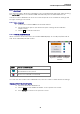
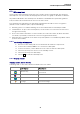
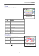
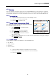
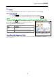
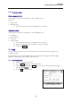
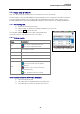
Table Of Contents
- Safety precautions
- Notes on use of these operating instructions
- CHAPTER 1 Your LanXPLORER
- AA Alkaline
- 4 hours under normal operating conditions
- Charging time:
- Operating temperature (min./max.):
- Storage temperature (min./max.):
- Relative humidity:
- 1.3. Equipment included Basic version
- 2.1. LanXPLORER
- 2.2. Power options
- 3.1. Principles
- 3.2. System
- 3.3. RJ45
- 3.4. Fibre-optic cable
- 3.5. Tests
- 3.6. IP
- 3.7. VLAN
- 3.8. WiFi
- 3.9. 802.1x
- 5.1. Ports
- 5.2. Passive wiring
- 5.3. Active wiring
- 5.4. Inline Test
- 5.5. Fibre-optic cable
- 5.6. WiFi
- 6.1. Test summary
- 6.2. Autotest
- 6.3. Wiremap test
- 6.4. Testing a passive route without remote / active Remote
- 6.5. Netmap
- 6.6. Verify
- 6.7. Ping
- 6.8. Voice over IP (VoIP)
- 6.9. Trace Route
- 6.10. Blink
- 6.11. Power over Ethernet (PoE)
- 6.12. Loop
- 6.13. PC Diagnosis
- 6.14. Statistics
- 6.15. WiFi
- 7.1. Safety precautions
- 7.2. Instructions for cleaning SFP modules and patch cables
- CHAPTER 2 Instrument description
- CHAPTER 3 Settings
- CHAPTER 4 Test summary
- CHAPTER 5 Test setup
- CHAPTER 6 Test description and procedure
- CHAPTER 7 Wiring test on fibre-optic conductors and SFP modules
- CHAPTER 8 LanXPLORER Firmware Update
- CHAPTER 9 Spare parts - Socket inserts

Chapter 6
Test Description and Procedure
43
6.3. Wiremap test
Short circuits, discontinuities and erroneous circuits can be localised with the aid of the
wiremap test. The test results are displayed in the form of a graph to facilitate evaluation.
Any faults indicated in the wiremap test should be remedied before performing further
tests, because this would result in errors in the other tests.
The wiremap test guarantees the following minimum thresholds for error recognition
(based on four conductor pairs, optional shielding):
All wiring errors or combined wiring errors are indicated in the wiremap as faults.
Combinations of up to three interruptions, short-circuits or reversed connections are
recognised correctly.
In the case of discontinuities or short-circuits, the end of the cable, at which the fault
occurred, is specified (on Autotest screen for length measurement).
Split pairs are recognised on the basis of specific patters of contradictory NEXT values
(near-end crosstalk).
6.3.1. Performing Wiremap test
1. Disconnect the cable path to be tested from all network components.
2. Connect the LanXPLORER to one end of the cable path.
3. Connect a remote / active Remote to the other end of the cable path.
4. Select the menu point "Tests" on the standby screen.
5. Select the menu point "Wiremap".
6. Select Run to start the Wiremap test.
6.3.2. Display results
Displays on the Active Remote
A flashing LED on the Active Remote indicates the test status:
LED display
Description
Red, slowly
The end is near has been detected – Test not
performed.
Fast red: Fault
Green, fast The end is near has been detected - Cable path is okay
Orange Incorrect voltage