
Manual

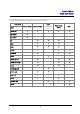
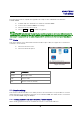
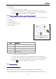
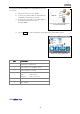
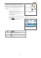
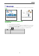
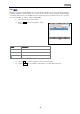
Table Of Contents
- Safety precautions
- Notes on use of these operating instructions
- CHAPTER 1 Your LanXPLORER
- AA Alkaline
- 4 hours under normal operating conditions
- Charging time:
- Operating temperature (min./max.):
- Storage temperature (min./max.):
- Relative humidity:
- 1.3. Equipment included Basic version
- 2.1. LanXPLORER
- 2.2. Power options
- 3.1. Principles
- 3.2. System
- 3.3. RJ45
- 3.4. Fibre-optic cable
- 3.5. Tests
- 3.6. IP
- 3.7. VLAN
- 3.8. WiFi
- 3.9. 802.1x
- 5.1. Ports
- 5.2. Passive wiring
- 5.3. Active wiring
- 5.4. Inline Test
- 5.5. Fibre-optic cable
- 5.6. WiFi
- 6.1. Test summary
- 6.2. Autotest
- 6.3. Wiremap test
- 6.4. Testing a passive route without remote / active Remote
- 6.5. Netmap
- 6.6. Verify
- 6.7. Ping
- 6.8. Voice over IP (VoIP)
- 6.9. Trace Route
- 6.10. Blink
- 6.11. Power over Ethernet (PoE)
- 6.12. Loop
- 6.13. PC Diagnosis
- 6.14. Statistics
- 6.15. WiFi
- 7.1. Safety precautions
- 7.2. Instructions for cleaning SFP modules and patch cables
- CHAPTER 2 Instrument description
- CHAPTER 3 Settings
- CHAPTER 4 Test summary
- CHAPTER 5 Test setup
- CHAPTER 6 Test description and procedure
- CHAPTER 7 Wiring test on fibre-optic conductors and SFP modules
- CHAPTER 8 LanXPLORER Firmware Update
- CHAPTER 9 Spare parts - Socket inserts

Chapter 5
Test Setup
37
This function allows all Ethernet-compatible devices to
be tested.
1. Select the menu "Ports" "RJ45".
2. Connect a network cable to the Ethernet-
compatible device to be tested.
3. Connect the free end of the cable path to
the RJ45 network port on the
LanXPLORER.
4. Select Detect to start recognition of the Ethernet-compatible device.
5.4. Inline Test
Item
Description
1
Line Rate and Duplex status (FD – Full
Duplex, HD – Half Duplex
2 Port number of compatible switch
3 Auto Negotiation On/Off
4
Recognition of power over Ethernet.
PoE - PoE present.
No-PoE - PoE not present.
5 IPv4 address
6 IPv6 address
Figure 33: Typical test setup for
an active cable path.
Figure 34: Active wiring test
1
2
3
4
5
6