
Manual
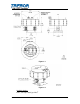

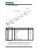

2.4 PARTS ILLUSTRATION
2.5 PARTS LIST
ILL
NO
PART NO QTY DESCRIPTION MATERIALS
1 AL003-01* 1 Union Nut
PVDF
2 AM022 1 Base, Mounting PP
3 AL056 1 Body, Inline ¾” Pillar Connection PFA
4 1700C0047 1 Diaphragm PTFE
5 J0093 1 Push Plate PTFE
6 AL019 1 Support Plate PTFE
7 AL014 1 Shaft PFA
8 AL001 1 Head PP
9 98002450 1 O-Ring FFKM
10 AL023 1 Pilot Seat PTFE
11 AK020 1 Pilot Poppet PFA
12 AK030 1 Pilot Cap Seal PTFE
13 AL004 1 Pilot Cap PP
14 C0102 1 Base, Quick Release PP
15 98003207 4 Screw, #4-20 X ¾”, FHSMS G.F. PP
* Available in other configurations
2.6 CLEAN-UP
To help remove potentially dangerous chemicals prior to service or shipment, the
surge Suppressor should be flushed with DI water or disassembled and
thoroughly cleaned. Allow DI water to flush in and out to prevent pressure build
up. Surge Suppressor can also be submerged in a rinse tank for clean up.
PAGE 6 SS95 SURGE OPERATION / MAINTENANCE MANUAL