Phone: 800-669-1303 or 801-561-0303 Fax: 801-255-2312 e-mail: treborservice@idexcorp.com SS95-X Surge Suppressor Operation / Maintenance Manual SERIAL NUMBER (located on top of product): PATENTS: U.S.
CONTENTS 1 2 3 INSTALLATION............................................................................................................3 1.1 UNPACKING ......................................................................................................3 1.2 LOCATING / MOUNTING SURGE.....................................................................3 MAINTENANCE ...........................................................................................................5 2.
1 INSTALLATION 1.1 UNPACKING After unpacking, the Surge Suppressor should be checked for any damage that may have occurred during shipment. Damage should be reported to the carrier immediately. The following items should be included within the shipping container: Qty 1 1 1.2 Item SS95-X MSS95-X Description SS95 Surge Suppressor Operation/Maintenance Manual LOCATING / MOUNTING SURGE • Run 1/8 bleed line to drain. In the event of a diaphragm failure fluid may flow through tube to drain.
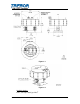
Figure 1-1 Figure 1-2 Available Options Inline, 3/4” Super 300 Type Pillar® PAGE 4 SS95 SURGE OPERATION / MAINTENANCE MANUAL
2 MAINTENANCE 2.1 PREVENTIVE MAINTENANCE SCHEDULE SS95-X Surge Suppressor 2 Year 1 Year Inspection 6 Month 4 Year 2 Year 1 Year Replacement X X X X 2.2 Component / Comments Poppet Pilot Valves and Seats Diaphragms Union Nut Retorque RECOMMENDED SPARE PARTS KRSS95-00-A Spares Rebuild Kit, which includes: Part No 1700C0047 98002450 AK020 AK030 AL023 2.3 Qty 1 1 1 1 1 Description Diaphragm O-ring Pilot Poppet Pilot Seal Pilot Seat Qty 1 1 1 1 1 Description Torque Wrench, 30-150 Ft. Lb.
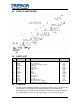
2.4 PARTS ILLUSTRATION 2.5 PARTS LIST ILL NO 1 2 3 4 5 6 7 8 9 10 11 12 13 14 15 * 2.
NOTE: When handling Surge Suppressor, wear appropriate personal protection gear, including safety glasses. 2.7 DISASSEMBLY During the life of the Surge Suppressor it may be necessary to perform certain preventative maintenance procedures to ensure its continued high performance. This Section and Section 2.9 Assembly are provided for the user’s convenience in disassembling and re-assembling the Surge Suppressor. • Thoroughly clean/flush the Surge Suppressor using DI water (See Section 2.6 Clean-Up).
2.9.a Head Assembly • Thread pilot seat into head using 3/4”. Light hand tight; do not over tighten, damage will occur. • Install pilot poppet into pilot seat in head. • Install seal and pilot cap into head tighten using 3/4” Pin Tool. 2.9.b Final Assembly PAGE 8 • Secure Head in bench mounted vice across the flats to prevent aesthetic damage use a protective barrier between vice and head. • Install shaft through support plate; thread push plate onto shaft hand tight.
3 WARRANTY SS95 SURGE SUPPRESSOR TREBOR International, Inc. warrants to the purchaser of new equipment manufactured by TREBOR to be free from defects in material and workmanship when used for its intended purpose under normal operating conditions, and maintained according to the Operation/Maintenance Manual.