
User Manual


4
•
TRAXXAS
SLASH 4X4 PLATINUM EDITION
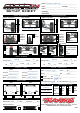
3. Remove the lower cap and the
X-ring from the shock body (B).
4. Use side cutters to grip the shock
shaft just above the rod end.
Remove the rod end from the
shock shaft using the suspension
multi-tool (C).
5. Remove the shock shaft
with piston from the shock
body out through the top of
the shock body.
Shock assembly
1. Replace the stock piston with
desired optional piston. Be careful
not to lose the small washer
located below the piston.
2. Position the new piston onto
the shock shaft above the small
washer. Grip the threads of
the shaft with side cutters or
needlenose pliers and tighten
the nut with the 4-way wrench to
secure the assembly (D).
3. Insert the shock shaft assembly
through the shock body until the
piston bottoms out.
4. Lubricate the shaft and X-ring
with silicone oil.
5. Install the X-ring over the
shaft and into the bore of the
shock body.
6. Install the lower cap using the
suspension multi-tool (B).
7. Grip the shaft close to the threads
with needlenose pliers or side
cutters and thread the rod end
onto the shock shaft until the rod
end bottoms out (C).
8. Fill the shock with new silicone
shock oil up to the top of the shock
body. Slowly move the piston
up and down (always keeping it
submerged in oil) to release the air
bubbles. Let the shock sit for a few
minutes to allow any remaining air
bubbles to surface.
9. Slowly thread the upper cap
with the installed shock bladder
onto the shock body with the
suspension multi-tool. The excess
oil will bleed out of the small hole
in the shock cap. Tighten the shock
cap until snug. Use the included
steel shock wrench to hold onto
the shock body while tightening
(A).
10. Reinstall the spring and lower
retainer.
Sway Bar Settings and Adjustments
• Adjust the sway bar links so the sway bars are level (parallel
to the ground) when the truck is on the ground and the
suspension is at rest (normal ride height). This allows equal
sway bar travel in both unloaded and loaded suspension
conditions. Always adjust the left and right sway bar links
equally to prevent suspension tweak.
• The adjustable hollow balls can be moved closer to or farther
from the sway bar mount (pivot point) to increase torsion
response and fine tune the
sway bar’s response for
different track conditions:
Closer to the pivot point
results in a stiffer setup, farther
from the pivot point will result
in softer sway bar response.
For smooth surfaces with high traction:
• Adjust linkage placement for stiffer response
(closer to the sway bar mount).
For rough surfaces with low traction:
• Adjust linkage placement for softer response
(farther from the sway bar mount).
To reduce understeer (pushing in corners):
• Adjust front linkage placement for softer response
(farther from the sway bar mount).
• Adjust rear linkage placement for stiffer response
(closer to the sway bar mount).
To reduce oversteer (loose in corners):
• Adjust front linkage placement for stiffer response
(closer to the sway bar mount).
• Adjust rear linkage placement for softer response
(farther from the sway bar mount).
Tuning the Center Differential
The center differential allows the power from the motor to be
transferred to the front and rear differentials independently from
one another. When the rear wheels are under more load than the
front wheels, more power will be transmitted to the front wheels.
This is very beneficial on rough terrain and makes hard acceleration
from low speeds easier to control by keeping the nose down. The
center differential is assembled with 100K differential lube from the
factory. This viscosity will be a good base point for most conditions.
Thinner fluid will transfer power more easily than thicker fluid. Try
thinner fluid on extremely rough and slick surfaces, and thicker
fluid on very smooth and high-bite surfaces. Traxxas offers silicone
differential fluid in a variety of viscosities:
Part #5135: 10K Part #5136: 30K Part #5137: 50K
Part #5130: 100K Part #5039: 500K
Follow these steps to remove and refill the differential:
1. Remove the two 4x12mm button-head cap screws from the
top of the chassis.
2. Remove the two 4x14mm button-head cap screws from the
bottom of the chassis.
3. Pull the rear suspension assembly away from the chassis.
4. Remove the center differential by pulling it away from the
rear gearbox.
Stiffer
Softer
Multi-tool Shock Functions
A. Tighten/Loosen Upper Cap
B. Tighten/Loosen Lower Cap
C. Remove/Install Rod End
7468
7468
7468
7463
7468
7463
7463
7463
F-7444
R-7446
7440 opt.
7442 opt.
7443 opt.
7447 opt.
7449 opt.
7441 opt.
7445 opt.
7448 opt.
7463
7464
Front (long)
7465
rear (xx-long)
7466
Front (long)
7467
rear (xx-long)
7463
(Rear Only)
7468
D. Piston Installation/Removal