
Product Info


Bluegiga Technologies Oy
Page 50 of 54
13 Layout Guidelines
13.1 WT21-N
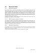
RF output can be taken directly from the RF test point (RFTP) of the module. RFTP has a signal
pin surrounded by a ground. Dimensions for the RFTP are shown in the figure below. Use 50
ohm trace to route RF from RFTP. With WT21-A leave RFTP floating and do not place copper
directly under RFTP.
Figure 33: Dimensions of the RFTP
13.2 WT21-A
Figure 34: Example layout