
User's Manual


Ranger v4.4 Installation Guide
Sep
2017
TRADE SECRET. Trapeze Proprietary and Confidential.Copyright © 2017 Trapeze Software ULC, its subsidiaries and affiliates. All rights reserved.
21
of 42
9 Connection Points
9.1 Splicing
T-Taps are not a suitable form of splicing into existing cabling. All splices must be soldered. Adhesive-lined heat
shrink must be applied for protection.
9.2 Power
Power connections should be made directly to the battery and fused as close to the battery as possible. Avoid
using a cigarette lighter or “Power Point” receptacles as power sources. Trapeze does not recommend wiring
power directly to a vehicle kill switch because the Ranger unit will not power down correctly. Appropriate fuses
are provided with the installation equipment.
Typically, powering the Ranger unit directly from the battery ensures that voltage drops are kept to a minimum. If
it is necessary to power the Ranger unit from an existing circuit, avoid using circuits that are used to power high
current accessories such as AC units, heaters, or wheel chair lifts.
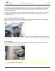
9.3 Ground Point
The ground point should be that point where the (-) terminal from the battery is connected to the body. Typically,
this connection to the battery is a 6 or 8 AWG black wire connected to the wheelhouse or radiator support.
Do not fuse the ground lead. If the ground-side fuse were to open, the entire supply current is conducted by an
alternate current return path, which may cause the feed line to overheat possibly resulting in damage.
9.4 Vehicle Speed Sensor for Odometer Pulses (Optional)
Most installations use the Ranger GPS receiver for mileage tracking, however, in some cases, a wired odometer
connection may be required. Many vehicles have a Vehicle Speed Sensor (VSS) point that provides a pulse train
from the transmission. Vehicles that do not have a VSS point with adequate signal characteristics require the
installation of a transducer. It is the responsibility of the installer and customer to locate a VSS point or determine
the appropriate location for a transducer. Your Customer Care representative may be able to assist in locating a
suitable VSS point. He/She can also provide information on the type of signal that is required for accurate
odometer tracking.
9.5 Emergency Switch (Optional)
The emergency switch is usually installed somewhere that would allow for covert operation. This location needs
to be chosen by the customer prior to the start of installation. A switch can be provided if required. It is
sometimes possible to use an existing switch already on the vehicle. Contact a Customer Care representative to
discuss your specific requirements.
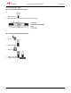
9.6 Switched Ignition Signal
The ignition sense input or Ranger V4.4 can be configured in two ways: standard ignition detection or alternator
charge voltage detection. Ranger V4.4 can be configured through software to use the alternator charge voltage
detection option. In this case connect the ignition sense line to the battery, otherwise, use an ignition signal from
It is important to utilize an unused ignition point. Connecting to an ignition point that is currently being used to
switch other devices can cause improper operation of those devices.