
User's Manual


Ranger v4.4 Installation Guide
Sep
2017
TRADE SECRET. Trapeze Proprietary and Confidential.Copyright © 2017 Trapeze Software ULC, its subsidiaries and affiliates. All rights reserved.
23
of 42
10 Cabling
10.1 Routing
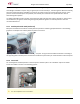
1. Use caution when routing wires between the passenger and engine compartments to avoid chafing or
pinching the wires. Use grommets over any exposed sharp edges and strain reliefs to keep wires in place. Seal
all holes to prevent moisture intrusion.
2. Route and secure all wiring under the hood away from mechanical hazards such as exhaust manifolds and
moving parts.
3. Avoid running power leads in parallel with vehicle wiring over long distances.
4. If cabling is routed under the instrument panel, be sure that there is no interference with the proper
operation of the foot controls.
10.2 Strain Relief
Ensure that there is no strain exerted on cable connectors where they enter the unit. Avoid placing the unit in a
position where the cable connectors entering the back of the unit are under pressure or strain of any kind.
Ensure the power cable is fully inserted before replacing the cable cover. In the event of undue stress or strain on
installed cables and connectors, permanent damage may occur that can weaken the connections. This may result
in intermittent or complete loss of communication and or power. Always include strain relief every 2-3 feet on
long cable runs.
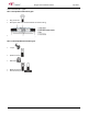
As the Ranger unit can be tilted and rotated freely by the driver/user, cabling should be installed such that
moving/adjusting the position of the unit does not exert any significant stress on the cables.
10.3 Labeling
It is important to always label cabling at connection points. This practice and using cables with consistent coloring
will make maintenance easier.
10.4 Wire Types
The following are the minimum specifications for the hook-up wire that should be used during the installation
process:
• Ranger Power and Ground
300V, 105°C PVC, 18AWG stranded
• Ignition
300V, 105°C PVC, 22AWG stranded
• Odometer Interface
300V, 105°C PVC, 22AWG stranded
• Ranger Inputs (example: Emergency Input)
300V, 105°C PVC, 22AWG stranded
10.5 Electrical Measurements
Always ensure that there is adequate voltage at the point where Ranger is being powered. Compare this voltage
to the voltage at the battery. The two voltages should be almost the same or a different power point should be
chosen closer to the battery.