
User's Manual


MultiConnectHardwareInstallationGuide 1_2.doc
April 8, 2004
Page 11 of 17
Suite 230, 2891 Sunridge Way NE, Calgary Alberta, T1Y 7K7
♦ Phone: (403) 777-3760 ♦ Fax: (403) 777-3769
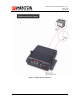
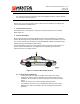
Figure 3: MultiConnect Interface points (Front View)
3.1 Interface Summary
1. Straight SMA Connector
Modem Antenna
2. 18pin Micro Fit Connector (MOLEX 43045-1806)
Power, Ignition Sense and Vehicle I/O
3. User Interface
LEDs to indicate – DSR, DTR, RXD, TXD, ONI (modem on), PWR (IGN on).
4. 8 position Modular Jack - RJ45 (AMP 406525-1)
RS232 Comm/Debug Port
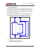
3.2 Vehicle Interface
Details regarding the cabling interface for external MultiConnect host devices (Mentor
Engineering’s MDC or a PC for instance), are available as application notes specific
to these functions. These notes are provided as required by Mentor Engineering, Inc.
See Interface Point #2 above.
4 Cabling
The MultiConnect receives power via the Mentor supplied power cable (4-CAS-
BBXVEHC075-00). Power and Ignition Sense lines need to be installed with the in-line
fuses provided. See cable pin-out for details.
It is common practice to route the cabling through the vehicle so it is not visible to the
driver and is protected from the environment. Mentor Engineering recommends that this
practice be followed in all installations.
If an external host device (i.e. an MDC) is being used with the MultiConnect, the installer
must ensure that there is a common ground between the devices. MultiConnect power
leads can be crimped onto the power leads at the power input to the host device.
Installing the power leads in this way will avoid the possibility of the ground potential at
MultiConnect differing from the ground potential of the host device (due to current draw
during a transmit cycle).
The MultiConnect should be installed to unswitched power. The unit can use the ignition
line to power on and off automatically, or it can use a power control input so that the host
device determines when the MultiConnect is on. The two methods can also be used in
conjunction with each other.
The in-line power fuse is a 3-amp MINI blade fuse (2-FUS-MINI003A-01). The power fuse
must be installed within 4” of the Vehicle Battery. The in-line ignition fuse is a 2-amp MINI
blade fuse (2-FUS-MINI002A-01). The Vehicle ignition line must be fused with the in-line
fuse provided or through the vehicle fuse box.
Note, a blown fuse will often indicate that there is either a problem with a connection to
the MultiConnect or with the MultiConnect itself. Check all connections before replacing a
fuse.