EP308 SpecificationsManual 06E00079-001A EzeFare Validator Manual Version Author A Approval date Approved by A.
EP308 SpecificationsManual 06E00079-001A Contents 1 Overview ............................................................................................................................. 4 2 References ......................................................................................................................... 4 3 Acronyms ............................................................................................................................ 4 4 Electromagnetic Specifications ........
EP308 SpecificationsManual 06E00079-001A 7.3 8 SAM Card Slots ........................................................................................................... 9 Interface Specifications/Recommendations......................................................................... 9 8.1 J1708 ........................................................................................................................... 9 8.2 RS232..........................................................................
EP308 SpecificationsManual 06E00079-001A 1 Overview This document is to provide the specifications and recommendations for the interconnection of the EzeFare Validator. 2 References [1] SAE J1708 Serial Data Communication Between Microcomputer Systems in Heavy-Duty Vehicle Applications Aug 2004 [2] SAE 1939-11 Physical Layer, 250K bits/s, Twisted Shielded Pair Oct 1999 [3] Telit Jupiter JF2 Datasheet [4] IEEE 802.
EP308 SpecificationsManual 06E00079-001A 4 Electromagnetic Specifications Note: This equipment has been tested and found to comply with the limits for a Class A digital device, pursuant to Part 15 of the FCC Rules. These limits are designed to provide reasonable protection against harmful interference in a residential installation.
EP308 SpecificationsManual 06E00079-001A 5 Environmental The EzeFare Validator is designed to meet the following specifications but is not tested to meet SAE J1455. 5.1 Temperature Operating: -20°C - + 60°C Storage: -30°C - +70°C 5.2 Shock and Vibration Swept Sinusoidal: 10 – 2000 Hz @ 2 g Survive and impact velocity of 1.75 m/s on all edges and corners 5.3 Electrostatic Discharge Packaging and Handling: Tested to +/- 4kV direct contact discharge.
EP308 SpecificationsManual 06E00079-001A 6 Connectors 6.1 RS232 6.1.1 Connector Connector: IP67 D-SUB 9 Male Mating Connector: IP67 D-SUB9 Female, or equivalent 6.1.2 Pinout Pin Signal Number 2 RXD 3 TXD 5 GND 7 RTS 8 CTS Signal Type RS232 Receive Data RS232 Transmit Data RS232 GND RS232 Request to Send RS232 Clear to Send 6.2 Power 6.2.1 Connector Connector: Molex 0306-2044 Mating Connector: Molex 0306-1043 or equivalent 6.2.
EP308 SpecificationsManual 06E00079-001A Pin Number 3 4 5 Signal Signal Type INPUT3 INPUT4 INPUT5 Discrete Input Discrete Input Discrete Input 6.4 J1708 6.4.1 Connector Connector: Molex 0306-2032 Mating Connector: Molex 0306-1038 or equivalent 6.4.
EP308 SpecificationsManual 06E00079-001A 6.5 Ethernet 6.5.1 Connector Connector: D-SUB 50 Male Mating Connector: D-SUB 50 Female, AMP 1658641-3 or equivalent 6.5.1 Pinout Pin Signal Number 1 TPI+ 2 TPI3 TPO4 TPO+ 5 SHIELD Signal Type Data In+ Data InData OutData Out+ Ground 7 Card Interfaces 7.1 Micro-SD Card Slot One MicroSD card slot for removable memory storage. 7.2 SIM Card Slot One Mini-SIM (2FF) card slot. 7.3 SAM Card Slots Two Secure Access Module card (2FF) slots.
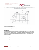
EP308 SpecificationsManual 06E00079-001A Figure 8-1 Note: C1 and C2 are 0 Caution: An RS-485 specified termination uses a 100 ohm resistors external to each node at each end of the bus which if installed in a J1708 system can cause the network to fail. 8.2 RS232 The minimum/maximum voltages on the bus are specified to be +/-15V. A ‘0’ is +5 to +15V and a ‘1’ is -5 to -15V. Voltages between -3V and +3V are undefined by the standard.
EP308 SpecificationsManual 06E00079-001A 8.3 Digital Inputs VIL < 0.5V and VIH 1.2V. These inputs are protected with 47K of series resistance. Transients to 60V can be tolerated with circuit damage becoming more likely above 60V. 8.4 Audio The speaker is rated to 3W, 200 – 20,000 Hz. 8.5 GPS The EzeFare Validator uses an internal GPS antenna. Specifications taken from Telit Jupiter JF2 DatasheetError! Reference source not found..