
User's Manual


Chapter 13: Client IP Configuration
TR0153 Rev. E1 104
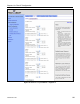
interface. Addresses for the remaining client access interfaces are determined by successively
incrementing the Base Address by 1. It is recommended that the gateway in a mesh
neighborhood be assigned the lowest available value (3 in the example in the CLI section
below) and the repeaters in the mesh neighborhood are given successively higher values, with
an increment of 5 between them (5 is the maximum number of client access interfaces
available on each mesh device, including the Ethernet interface on mesh repeaters).
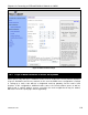
Layer 2 emulation must also be enabled when operating in centralized DHCP server mode.
This setting is located on the “System” tab of the “System” page of the web interface. See
section 18.2 for more information on layer 2 emulation mode.
CLI
Centralized DHCP server mode is enabled using the ‘dhcp.relay.enable’ and
‘l2.client_mac_fwd’ parameters in the ‘sys’ interface as shown in the example below.
> use sys
sys> set dhcp.relay.enable=yes
sys> set l2.client_mac_fwd=yes
In the example below, the central DHCP server and next WAN router reside on the same
segment to which the mesh gateway’s wired interface is connected.
> use sys
sys> set dhcp.relay.server=192.168.5.2
sys> set dhcp.relay.gateway=192.168.5.1
The example below shows how to set the DHCP mode parameters for the wlan1 and wlan2
interfaces.
> use wlan1
wlan1> set dhcp=server
wlan1> set wlan1.dhcp.relay.enable=yes
> use wlan2
wlan2> set dhcp=server
wlan1> set wlan2.dhcp.relay.enable=yes
To disable distribution of centralized DHCP addresses on an interface, set the interface’s
‘dhcp.role’ parameter to ‘none’ as shown below.
> use wlan3
wlan3> set dhcp=none
The Client Address Space value is set with the ‘dhcp.relay.dhcp_subnet’ parameter in the ‘sys’
interface. This value should be a class A, B, or, C subnet specified using CIDR notation as
shown in the example below.
> use sys
sys> set dhcp.relay.dhcp_subnet=192.168.5.0/24