
User's Manual


Chapter 13: Virtual Access Point (VAP) Configuration
TR0190 Rev. A1 75
13.1 Virtual Access Point Interfaces
There are four interfaces that are used to configure the VAPs: wlan1, wlan2, wlan3, and wlan4.
The VAPs have equivalent configuration capabilities and there is no inherent prioritization or
preference for one VAP. The section on quality-of-service settings (section 17) describes how
prioritization on a per-VAP basis can be configured.
13.2 Enabling and Disabling Virtual Access Points
VAPs can be individually enabled or disabled. A VAP can be configured when it is disabled
and parameter settings are retained when it is disabled.
CLI
A VAP can be enabled with the ‘enable’ parameter in the ‘wlanN’ interface as shown below.
> use wlan1
wlan1> set enable=yes
A VAP can be disabled with the following commands.
> use wlan1
wlan1> set enable=no
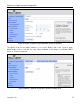
Web GUI
Each VAP can be enabled or disabled by setting the “State” parameter via the web interface
using the appropriate “wlanN” tab on the “Wireless Interfaces” page (see Figure 41).
13.3 Virtual Access Point Client Device Address Space
Each VAP interface is either assigned a segment of the TR-900’s class C client address
space, if the device is using implicit addressing mode, or an arbitrary address space can be set
for the interface when using the explicit addressing scheme . See section 10 for more
information on client addressing schemes.
The TR-900 VAPs’ interface IP configurations can be changed directly when it is using the
explicit addressing scheme. They cannot be changed directly when the device is using the
implicit addressing scheme.
When an TR-900 is configured to use the implicit addressing scheme, set the IP address to the
desired value by modifying the node ID and LAN prefix parameters (see sections 9.2 and