
User's Manual


Chapter 1: Working with the ER-1000
TR0190 Rev. A1 10
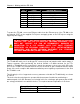
Pin Signal Standard Wire Color
1 Tx+ White/Orange
2 Tx- Orange
3 Rx+ White/Green
4 PoE V+ Blue
5 PoE V+ White/Blue
6 Rx- Green
7 Gnd White/Brown
8 Gnd Brown
Table 3. Ethernet port pinout
To power the TR-900, connect an Ethernet cable from the Ethernet port of the TR-900 to the
port labeled “CPE” on the supplied PoE injector and apply power to the PoE injector using the
supplied power supply
DO NOT CONNECT ANY DEVICE OTHER THAN THE TR-900 TO THE PORT
LABELED “CPE” ON THE PoE INJECTOR. NETWORK EQUIPMENT THAT
DOES NOT SUPPORT PoE CAN BE PERMANENTLY DAMAGED BY
CONNECTING TO A PoE SOURCE. NOTE THAT MOST ETHERNET
INTERFACES ON PERSONAL COMPUTERS (PCs), LAPTOP/NOTEBOOK
COMPUTERS, AND OTHER NETWORK EQUIPMENT (E.G. ETHERNET
SWITCHES AND ROUTERS) DO NOT SUPPORT PoE.
1.2.2 Antenna
The TR-900 AP radio port is an N-type RF connector that can interface with a wide range of
Tranzeo antennas. After purchasing the desired 2.4GHz or 5.8GHz antenna (for the TR-
900HG or TR-900HA models respectively), attach the antenna to the access point (AP) radio
port on the TR-900. The antenna must be chosen such that its gain combined with the output
power of the radio complies with maximum radiation power regulatory requirements in the area
the TR-900 is used.
The following is a list of supported accessory antennas sold with the TR-900 family, as shown
in Table 2.
This device has been designed to operate with the antennas listed below, and having a
maximum gain of 32 dBi. Antennas not included in this list or having a gain greater than 32 dBi
are strictly prohibited for use with this device. The required antenna impedance is 50 ohms.
Tranzeo Part Number Antenna Type
TR-OD900-12 Omni
TR-900H-120-12 Horizontal Sector