SISTP10xx-141-LR(T) 10/100Base-TX to 100Base-FX Industrial PoE Switch Installation Manual Rev.
Transition Networks Table of Contents Trademark, copyright, and product classification information ......................................................................... iii Trademark.................................................................................................................................................. iii Copyright restrictions ................................................................................................................................. iii FCC warning .....
Transition Networks SISTP10xx-141-LR(T) Industrial PoE Switch In this section ............................................................................................................................................20 Advanced Features........................................................................................................................................21 TM AutoCross ........................................................................................................................
SISTP10xx-141-LR(T) Industrial PoE Switch Transition Networks Trademark, copyright, and product classification information Trademark All trademarks and registered trademarks are the property of their respective owners. Copyright restrictions © 2008 Transition Networks: All rights reserved. No part of this work may be reproduced or used in any form or by any means—graphic, electronic, or mechanical—without written permission from Transition Networks. Printed in the U.S.A.
Transition Networks SISTP10xx-141-LR(T) Industrial PoE Switch About this product and manual Industrial PoE Switch The SISTP10xx-141-LR(T) unmanaged Industrial PoE Switch provides (4) 10/100Base-TX (RJ-45) copper ports with Power over Ethernet injection and a 100Base-FX fiber connection with a fixed optical transceiver. These switches are hardened devices designed to reliably operate in harsh environments such as those found on factory floors, outdoor enclosures or other hazardous environments.
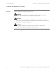
SISTP10xx-141-LR(T) Industrial PoE Switch Transition Networks Cautions and warnings Cautions and warnings Make sure that you read and understand all content identified by these two symbols: Cautions and warnings appear here and throughout this manual where appropriate. Failure to read and understand the information identified by the “caution” and “warning” symbols could result in poor equipment performance, damage to equipment, or injury to persons.
Transition Networks SISTP10xx-141-LR(T) Industrial PoE Switch Cautions and warnings, continued Warnings Warnings indicate the possibility of injury to persons. WARNING Be sure to disconnect power before installing and wiring the Industrial PoE Switch. Failure to observe this warning could result in an electrical shock. WARNING Fiber optics: Visible and invisible laser radiation when open: DO NOT stare into the beam, or directly view the beam with optical instruments.
Section I SISTP10xx-141 Industrial PoE Switch In this section These are the topics: Topic General description SISTP10xx-141 Industrial PoE Switch model numbers Package Contents Physical Description See Page 2 3 4 5
Transition Networks SISTP10xx-141-LR(T) Industrial PoE Switch General description Overview The SISTP10xx-141 unmanaged Industrial PoE Switch can help eliminate EMI or RFI issues and help to overcome distance limitations with copper-based cabling by providing a fiber interface to transport data from copper-based industrial networking and communication devices over fiber optic cabling.
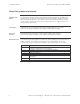
SISTP10xx-141-LR(T) Industrial PoE Switch Transition Networks SISTP10xx-141 Industrial PoE Switch part numbers Standard models The part numbers shown in Tables 1 and 2 perform as described in this manual. Table 1: Industrial PoE Switch Part Numbers Standard Operating Temperature (-10°C to +50°C) Part Number Ports 1-4: 10/100Base-TX SISTP1011-141-LR RJ-45 100 m (328ft) SISTP1013-141-LR RJ-45 100 m (328ft) SISTP1014-141-LR RJ-45 100 m (328ft) Port 5: 100Base-FX ST, 1300 nm multimode 2 km (1.
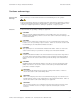
Transition Networks SISTP10xx-141-LR(T) Industrial PoE Switch Package contents Package contents Quantity 1 1 2 8 1 Description 10/100Base-TX to 100Base-FX Industrial PoE Switch DIN-Rail mounting bracket (installed) Wall mount brackets Screws (for attaching wall-mount bracket) Installation manual CD Compare the package contents of your industrial PoE Switch with the standard checklist above. If any item is damaged or missing, please contact Transition Networks Technical Support.
SISTP10xx-141-LR(T) Industrial PoE Switch Transition Networks Physical description Physical dimensions Width: 1.2” [30mm] Height: 5.5” [140mm] Depth: 3.
Transition Networks SISTP10xx-141-LR(T) Industrial PoE Switch Physical description, continued Bottom panel The top view of the Industrial PoE Switch is shown in Figure 2 with corresponding descriptions listed below: 6-position terminal block Grounding Screw Secondary power input terminals (2) Contact relay output terminals (2) Primary power input terminals (2) Figure 2: SISTP10xx-141-LR(T) Industrial PoE Switch (Top View) Back panel The back view of the Industrial PoE Switch is shown in Figure 3
Section II Installation In this section These are the topics: Topic DIN rail mounting Wall mounting Grounding the Industrial PoE Switch Connecting power to the Industrial PoE Switch Connecting an alarm fixture Connecting fiber cable Connecting copper cable Light Emitting Diodes (LEDs) See Page 8 10 11 12 15 17 18 19
Transition Networks SISTP10xx-141-LR(T) Industrial PoE Switch DIN rail mounting DIN rail clip The Industrial PoE Switch includes an aluminum DIN Rail Clip attached to the rear panel. Verify the clip is attached and oriented as pictured in Figure 4 below.
SISTP10xx-141-LR(T) Industrial PoE Switch Transition Networks DIN rail mounting, continued DIN rail mounting To mount the Industrial PoE Switch to the DIN rail, see Figure 5 and do the following: Step Action 1. Align and then position DIN-Rail-clip spring to the top of the DIN rail as shown in Figure 5, step (a). 2. Press DOWN on the Industrial PoE Switch and then IN to snap it into place on the DIN Rail. See Figure 5, step (b).
Transition Networks SISTP10xx-141-LR(T) Industrial PoE Switch Wall mounting Wall mount bracket The Industrial PoE Switch includes wall mount brackets and screws in the contents of the shipping package. The wall mount brackets can be attached to the top and bottom panels of the Industrial PoE Switch to enable mounting to a vertical surface such as the wall of an enclosure. Locate the brackets (2) and screws (8) and follow the steps below to install the brackets on the Industrial PoE Switch.
SISTP10xx-141-LR(T) Industrial PoE Switch Transition Networks Grounding the Industrial PoE Switch CAUTION Be sure to disconnect the Industrial PoE Switch from the DC power source before installing and wiring the device. Wiring considerations The following wiring considerations are recommended: • Signal lines must not be directly connected to outdoor wiring. • Use separate paths or conduits to route wiring for power and device data cables.
Transition Networks SISTP10xx-141-LR(T) Industrial PoE Switch Connecting power to the Industrial PoE Switch Redundant power inputs The Industrial PoE Switch has dual (redundant) power inputs capable of auto-sensing the input voltage, while providing over current protection and reverse polarity protection. The dual power inputs can be connected simultaneously to live DC power sources. See Figure 8.
SISTP10xx-141-LR(T) Industrial PoE Switch Transition Networks Connecting power to the Industrial PoE Switch, continued Note: Terminal-block wiring The terminal block can accept 12 – 24 AWG wire for power and alarm relay inputs. To wire the 6-position terminal block for redundant power, do the following: Note: Step 1. 2. 3. 4. 5. The 6-position terminal-block plug is constructed (keyed) to mate with the Industrial PoE Switch terminal block.
Transition Networks SISTP10xx-141-LR(T) Industrial PoE Switch Connecting power to the Industrial PoE Switch, continued Terminal-block wiring (continued) Step 6. Action Insert the terminal block plug into the Industrial PoE Switch’s terminal block, as shown in Figure 10. Figure 10: Wired Terminal Block Plug Inserted Into Industrial PoE Switch 7. 8. Note: Make sure that the DC power source is stable and clean.
SISTP10xx-141-LR(T) Industrial PoE Switch Transition Networks Connecting an alarm fixture Alarm relay The Industrial PoE Switch has dry relay contacts for connecting an external alarm fixture. Located on the green terminal block on the top panel, the relay has “normally open” contacts that can be wired to form a circuit for triggering an external alarm when a fault occurs (light or audible alarm). See Figure 11.
Transition Networks SISTP10xx-141-LR(T) Industrial PoE Switch Connecting an alarm fixture, continued Fault indications Wire the relay contacts to any warning light or audible alarm in the control room as shown in Figure 13. When a fault occurs, the relay contacts open, stopping the flow of current through the contact circuit. This will disable the external alarm or turn OFF a light, indicating a fault.
SISTP10xx-141-LR(T) Industrial PoE Switch Transition Networks Connecting fiber cables Fiber cable installation When connecting fiber cables to the 100BASE-FX port on the Industrial PoE Switch, make sure the correct type is used: ST or SC. To install the fiber cables, do the following: Step 1. Action Remove and keep the fiber-port protective dust cover(s).
Transition Networks SISTP10xx-141-LR(T) Industrial PoE Switch Connecting copper cables Copper cable installation To connect the copper cable to the Industrial PoE Switch and other equipment, do the following: Step 1. 2. 3. 4. Action Locate or build 10Base-T or 100Base-TX compliant copper cables with male, RJ45 connectors installed at both ends. Connect the RJ-45 connector at one end of the cable to the RJ-45 port on the Industrial PoE Switch. See Figure 15 below.
SISTP10xx-141-LR(T) Industrial PoE Switch Transition Networks Light Emitting Diodes (LEDs) LEDs The Industrial PoE Switch has LED indicators located on its front panel. The LEDs present ata-glance network status, and provide real-time connectivity information. Figure 17 shows the LEDs and a chart that explains the function of each.
Section III: Advanced Features Introduction This section provides an explanation of the advanced features on the Industrial PoE Switch.
SISTP10xx-141-LR(T) Industrial PoE Switch Transition Networks Advanced Features AutoCross TM TM AutoCross automatically detects and configures the twisted pair port on the converter to the correct MDI or MDI-X configuration allowing either straight-through (MDI) or crossover (MDI-X) cables to be used – see figure 18. No user intervention is required.
Transition Networks SISTP10xx-141-LR(T) Industrial PoE Switch Section IV: Cable Specifications Introduction This section provides copper and fiber cable specifications.
SISTP10xx-141-LR(T) Industrial PoE Switch Transition Networks Copper (RJ-45) cable specifications Copper cabling Shielded twisted-pair (STP) or unshielded twisted-pair (UTP) cabling may be used and can be configured as either Straight-through or crossover – see figure 19.
Transition Networks SISTP10xx-141-LR(T) Industrial PoE Switch Fiber cable and optic specifications Fiber cable characteristics Fiber optic specifications Cable physical characteristics must meet or exceed IEEE 802.3™ specifications. Parameter Specification Bit Error Rate: Single mode fiber: Multimode fiber: Multimode fiber: <10 9 µm 62.
SISTP10xx-141-LR(T) Industrial PoE Switch Transition Networks Section V: Troubleshooting Introduction This section provides basic troubleshooting information for the Industrial PoE Switch via a problem and corrective action table. The problems are stated in the problem column and the action(s) to take for the problem is stated in the corrective action column.
Transition Networks SISTP10xx-141-LR(T) Industrial PoE Switch Troubleshooting problem and corrective action table Problem Industrial PoE Switch does not power up Potential Cause • Is the wired terminal-block plug fully inserted into the Industrial PoE Switch? Potential Solution • Wire and insert the terminal-block plug into the Industrial PoE Switch’s terminal block – See pages 12-14 • Is the power LED lit? • Check that DC power is at the recommended levels. • Contact Technical Support.
Section VI: Contact Us, Warranty, & Compliance Information Introduction This section explains how to contact Transition Networks via Phone, fax, email, and direct mail.
Transition Networks SISTP10xx-141-LR(T) Industrial PoE Switch Contact us Technical support Technical Support is available 24 hours a day. United States: 1-800-260-1312 International: 00-1-952-941-7600 Live Web chat Chat live via the Web with a Transition Networks Technical Support Specialist. Log onto www.transition.com and click the Transition Now link. Web-based training Transition Networks provides 8-10 seminars per month via live web-based training. Log onto www.transition.
SISTP10xx-141-LR(T) Industrial PoE Switch Transition Networks Warranty Limited lifetime warranty Effective for products shipped May 1, 1999 and after, every Transition Networks’ labeled product will be free from defects in material and workmanship for its lifetime. This warranty covers the original user only and is not transferable.
Transition Networks SISTP10xx-141-LR(T) Industrial PoE Switch Warranty, continued Customer pays non-compliant return costs The customer must pay the non-compliant product(s) return transportation cost to Transition Networks for evaluation of said product(s) for repair or replacement. Transition Networks will pay for shipping the repaired or replaced in-warranty product(s) back to the customer (any and all customs charges, tariffs, or/and taxes are the customer’s responsibility).
SISTP10xx-141-LR(T) Industrial PoE Switch Transition Networks Compliance information Compliances CISPR22/EN5022 Class A + EN55024; EN60950 Class A; FCC Class A; CE Mark UL Listed; C-UL Listed The following part numbers are UL Listed: SISTP1011-141-LR, SISTP1011-141-LRT, SISTP1013-141-LR, SISTP1013-141-LRT, SISTP1014-141-LR, SISTP1014-141-LRT. (Canada) FCC Regulations This equipment has been tested and found to comply with the limits for a Class A digital device, pursuant to part 15 of the FCC rules.
Transition Networks European Regulations, (continued) SISTP10xx-141-LR(T) Industrial PoE Switch In accordance with European Union Directive 2002/96/EC of the European Parliament and of the Council of 27 January 2003, Transition Networks will accept post usage returns of this product for proper disposal. The contact information for this activity can be found in the ‘Contact Us’ portion of this document. CAUTION: RJ connectors are NOT INTENDED FOR CONNECTION TO THE PUBLIC TELEPHONE NETWORK.
Appendix A: Technical Specifications SISTP10xx-141-LR(T) specifications, notices, and warnings Parameter Standards Regulatory Compliance for Emissions Safety Compliance EMI Compliance Environmental Compliance Ports Fiber Optic Specifications Max Distance Max Data Rate Signals MAC address table Power Consumption Ingress Protection MTBF (MIL-HDBK-217F) Input Power Dimensions Weight Shipping weight Standard Operating Temperature (-LR models only) Extended Operating Temperature (-LRT models only) Storage T
Transition Networks SISTP10xx-141-LR(T) Industrial PoE Switch SISTP10xx-141-LR(T) specifications, notices, and warnings, continued Notices • The information in this user’s guide is subject to change. For the most up-to-date information on the SISTP10xx-141-LR(T) Industrial PoE Switch, please refer to the user’s guide on-line at: www.transition.com. • Product is certified by the manufacturer to comply with DHHS Rule 21/CFR, Subchapter J applicable at the date of manufacture.