™ StackMaster TR Active Retiming Managed Hub SMHB-TR-16 #7361.
CAUTION: RJ connectors are NOT INTENDED FOR CONNECTION TO THE PUBLIC TELEPHONE NETWORK. Failure to observe this caution could result in damage to the public telephone network.
Table of Contents Preface . . . . . . . . . . . . . . . . . . . . . . . . . . . . . . . . . . . . . . . . . . . . . . . . . . . . iii 1. INTRODUCTION . . . . . . . . . . . . . . . . . . . . . . . . . . . . . . . . . . . . . . . . . . . . 1–1 2. SITE PLANNING . . . . . . . . . . . . . . . . . . . . . . . . . . . . . . . . . . . . . . . . . . . . . 2–1 2.1 Site Considerations . . . . . . . . . . . . . . . . . . . . . . . . . . . . . . . . . . . . . . . 2–1 2.2 Network Parameters Data Sheets . . . . . . . . .
5.3 Replacement Procedures . . . . . . . . . . . . . . . . . . . . . . . . . . . . . . . . . .5–5 Replacing StackMasterTR Unit Fuses . . . . . . . . . . . . . . . . . . . . . . . . .5–5 5.4 StackMasterTR Field Upgrades . . . . . . . . . . . . . . . . . . . . . . . . . . . . . .5–6 Installing SNMP Management Board . . . . . . . . . . . . . . . . . . . . . . . . . .5–6 5.5 Software Upgrades . . . . . . . . . . . . . . . . . . . . . . . . . . . . . . . . . . . . . . .
Preface This guide is intended for the system or network administrator responsible for installing, configuring, using, and maintaining a Transition Engineering StackMaster™TR. A working knowledge of local area network (LAN) operations, including familiarity with communications protocols used on interconnected LANs, is assumed.
1. Introduction The TRANSITION Networks 16-Port StackMaster™TR Active Retiming Managed Hubs are designed for building SNMP managed token ring LANs using twisted pair cable.
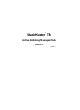
Connectors Ring In/Ring Out Connector 16 Port StackMaster™ TR Active Retiming Managed Hub Normal Insert n e t w o r k s 1 Lobe Ports 2 3 4 5 6 7 8 9 10 11 12 13 14 15 16 Expansion Card Indicators Enable T R A N S I T I O N P 4 Mbps P Status OFF 1 2 3 4 ON 5 6 7 8 Power Reset A 16 Mbps Ring In A Ring Out ZDL R ing Out Ring In An RJ-45 Ring In connector and an RJ-45 Ring Out connector are provided at the front of the 16-Port StackMaster™TR Active Retiming Managed Hub.
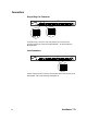
1. INTRODUCTION Connectors at Back Cascade (Bus) Connectors Cascade Connectors T R A N S I T I O N A n e t w o r k s Serial AUX Mpls, MN 55344 B Model#: SMHB-TR-16 Serial Caution : For continued protection against risk of fire, replace only with same type and rating of fuse : 250V 2A. Caution : Disconnect power before replacing fuse.
Indicators Power LED 16 Port StackMaster™ TR Active Retiming Managed Hub Normal Insert n e t w o r k s 1 Lobe Ports 2 3 4 5 6 7 8 9 10 11 12 13 14 15 16 Expansion Card Indicators Status Enable T R A N S I T I O N P 4 Mbps P OFF 1 2 3 4 ON 5 6 7 8 Power Reset 16 Mbps A Ring In Ring Out A ZDL Power When the StackMaster™TR 16-Port Unit is powered, the Power indicator is illuminated.
1.
Switches Active/Passive Switches P P A A 16 Port StackMaster™ TR Active Retiming Managed Hub Normal Insert n e t w o r k s 1 Lobe Ports 2 3 4 5 6 7 8 9 10 11 12 13 14 15 16 Expansion Card Indicators Status Enable T R A N S I T I O N 4 Mbps P 16 Mbps A P OFF 1 2 3 4 ON 5 6 7 8 Power Reset Ring In A Ring Out ZDL A(ctive) and P(assive) switches are provided for the Ring In port and for the Ring Out port for connection to active ( “A” ) or to passive (“P”) hubs.
1. INTRODUCTION 4Mbps/16Mbps Switch 16 Port StackMaster™ TR Active Retiming Managed Hub Normal Insert n e t w o r k s 1 Lobe Ports 2 3 4 5 6 7 8 9 10 11 12 13 14 15 16 Expansion Card Indicators Enable T R A N S I T I O N 4 Mbps P 16 Mbps A P Status OFF 1 2 3 4 ON 5 6 7 8 Power Reset Ring In A Ring Out ZDL 4 Mbps 16 Mbps The 4Mbps/16Mbps Speed Selection Switch allows selection of data rate (4Mbps or 16Mbps).
2. Site Planning Site planning for the StackMasterTR Stack requires consideration both of site conditions and of token ring standards. 2.
2.2 Network Parameters Data Sheets NOTE: SNMP network management is optional. The network parameter data sheets are intended to be a permanent record of site-specific network parameter values that will be required for configuring SNMP network management. TCP/IP Network Parameters Data Sheet CATEGORY StackMasterTR DEFAULT SITE ENTRY IP address (ipaddr) Management station to which asynchronous SNMP reports will be sent. Format: xxx.xxx.xxx.xxx EXAMPLE: 192.251.144.253 192.251.144.
2. SITE PLANNING SNMP Network Parameters Data Sheet CATEGORY StackMasterTR DEFAULT SITE ENTRY (commwrite) Security permission Format: PRIVATE/PUBLIC PRIVATE Authorization (auth) Security identifier Format: DISABLE/ENABLE DISABLE System name (sysname) Site-specific identifie -- usually. the host name. Format: Up to 256 characters NONE Location (location) Site-specific identifie -- usually. the host name.
Serial Port Parameters Data Sheet CATEGORY StackMasterTR DEFAULT SITE ENTRY Transmission rate (bps) Transmission speed, in bits per second Format: 9600/ 9600 Name (stop bitse) Serial protocol definition entry. Format: NONE/1 1 (data bits) Serial protocol definition entry. Format: NONE/1 8 (parity) Optional error checking entry Format: NONE/1 NONE Table 2-3.
3. Installation To install the StackMaster™TR 16-Port Active Retiming Managed Hub:: • Unpack the StackMaster™TR Equipment • Stack Units in Rack or on Table • Cascade StackMaster™TR Units • Connect StackMaster™TR to Network • Connect Units to Power • Optionally Configure SNMP Network Management 3.
3.2 Stacking Units in Rack or on Table NOTE: StackMaster™TR 16-Port Units are shipped with attached brackets for standard 19-inch rack installation and with attachable feet for table-top installation. 3.2.1 Standard 19-Inch Rack Installation CAUTION: The StackMaster™TR 16-Port Unit with the SNMP Management Board must be installed at the top of the stack. Failure to observe this caution will invalidate the SNMP network management.
3. INSTALLATION 3.2.2 Table-Top Installation NOTE: StackMaster™TR 16-Port Units are shipped with a separate, unattached set of adhesive-backed rubber feet. CAUTION: The rubber feet MUST BE INSTALLED on the StackMaster™TR 16-Port Unit if a StackMaster™TR 16-Port Unit is installed on a table-top or other flat surface. Failure to observe this caution could cause the StackMaster™TR 16-Port Unit to overheat and could result in data transmission failure and/or equipment damage.
3.3 Cascading StackMaster™TR Units Cascading the StackMaster™TR cascades ONLY the SNMP management. To cascade the StackMaster™TR units, use the RI/RO connections at the front. NOTE: Use only the special six-inch DB-25 (male-to-male) cables (PN 6005).The StackMaster™TR 16-Port DOES NOT require terminators. To cascade a Stack in which the top unit has an SNMP management board installed: 1. Connect six-inch DB-25 (male-to-male) cable to Cascade B of StackMaster™TR 16-Port Unit.
3.4 3. INSTALLATION Connecting StackMaster™TR to Token Ring Network When NO connection to RI port: • ALWAYS set Ring In switch to Active position. NOTE: The INSERT LED should remain OFF. When NO connection to RO port: • ALWAYS set Ring Out switch to Active position. NOTE: The NORMAL LED should remain OFF.
3.5 Connecting Units to Power The StackMaster™TR 16-Port Stack is connected to power by connecting each of the StackMaster™TR 16-Port Units to power. NOTE: Connect StackMaster™TR 16-Port Units from bottom to top. To connect the StackMaster™TR 16-Port Stack to power: 1. At StackMaster™TR 16-Port Unit back, locate the Unit power receptacle and associated fuse. NOTE: Fuse must be installed at correct setting for power source voltage before connecting to AC outlet. 2.
3. INSTALLATION 3.6 Resetting StackMaster™TR 16-Port Stack NOTE: The StackMaster™TR 16-Port Stack must be reset during installation to initialize the internal software. Managed Stack • If the StackMaster™TR 16-Port Stack is managed, use a jewelers screwdriver, paper clip, or other small device to depress the reset switch inside the StackMaster™TR 16-Port Unit with SNMP Management installed. The entire StackMaster™TR 16-Port Stack will recycle and then resume normal operation.
3.7 Optionally Configuring SNMP Network Management at Attached Terminal To set SNMP management parameters through an attached terminal: • • • • Connect the StackMaster™TR 16-Port to an ASCII terminal or terminal emulator Bring up the StackMaster™TR 16-Port configuration software Reset the StackMaster™TR 16-Port Set Network and SNMP parameter values. Connecting to ASCII Terminal NOTE: The DB9 serial port on the StackMaster™TR 16-Port is a DTE device.
3. INSTALLATION Bringing up Configuration Software. NOTE: Refer to 1.6 for a detailed description of the StackMaster™TR 16Port Configuration Software Display available at the attached terminal. To bring up the StackMaster™TR 16-Port configuration software, at the attached terminal command line, enter: ^D (“control D”) The StackMaster™TR 16-Port Configuration Main Menu comes up.
Setting Network and SNMP Parameters SNMP Network Management is configured by setting network and SNMP parameter values. Network Parameters To set the Network parameter values at an attached terminal: 1. At the StackMaster™TR 16-Port Configuration Main Menu MAIN> prompt, type and enter: MAIN> ip The StackMaster™TR 16-Port Network Parameters Menu comes up: Network Parameters Menu ipaddr = 192.251.144.253 submask = 255.255.255.0 router = 0.0.0.0 name = NONE domain = NONE nameserver= 0.0.0.
3. INSTALLATION SNMP Parameters To set the SNMP parameter values: 1. To access the SNMP Parameters Menu, at the Network Parameters MAIN> prompt, type and enter: MAIN> snmp The StackMaster™TR 16-Port SNMP Parameters Menu comes up to provide guidance in setting parameters for data to be used by the external SNMP network management software: SNMP Parameters Menu commwrite auth sysname location = = = = PRIVATE DISABLE NONE NONE commread trap contact = PUBLIC = 0.0.0.
Resetting the StackMaster™TR 16-Port NOTE: The StackMaster™TR 16-Port can be reset in any of the following ways:. • Disconnect power cord to StackMaster™TR 16-Port unit with installed SNMP management board, then reconnect the power cord.
4. Operation 4.1 Power On/Power Off The StackMaster™TR 16-Port Stack is powered ON when the power cords are connected from all the StackMaster™TR 16-Port Units to AC outlets. NOTE: When powered, the POWER LED on each StackMaster™TR 16Port Unit should be illuminated. The StackMaster™TR 16-Port Stack is powered OFF when the power cords are disconnected from all the StackMaster™TR 16-Port Units or from all the AC outlets.
5. Maintenance Maintenance of the StackMaster™TR 16-Port Stack is required only when a StackMaster™TR 16-Port unit fails. Recovery of a failed StackMaster™TR 16-Port unit requires fault isolation, using methods provided in this section, and corrective action. Corrective action is taken by simple procedures described in this section or by contacting TRANSITION Networks Technical Support. 5.1 Fault Isolation Use Table 5-1 for troubleshooting the StackMaster™TR 16-Port Stack.
5-2 Insert RI LED not illuminated and RI connected to active hub RO port The active hub’s RO port may be configured as passive. Switch RO to “P” (passive) position. Normal RO LED not illuminated and RO connected to active hub RI port The active hub’s RI port may be configured as passive. Switch RI to “P” (passive) position. Lobe Port LED not illuminated Cable failure (open/short). Check cable assembly or tester or swap cable with known good cable. Incorrect RJ45 cable installed.
5. MAINTENANCE Unit “freezes”. Cannot manage stack RI, RO switches are in passive position but one port is not connected. Set unconnected port switch to “A”(active) position. ZDL disabled and wrong speed station tries to insert. Switch ZDL to ON and reset hub. RI or RO cable broken while in “Passive” position. Replace cable. Stack initialization Reset Stack (See 5.2 Incorrect management cable used. Replace cable. Table 5-1.
5.2 Recovery Procedures Recovery of a failed StackMaster™TR 16-Port Unit or Stack is accomplished, often, by resetting the StackMaster™TR 16-Port Stack Managed Stack • If the StackMaster™TR 16-Port Stack is managed, use a jewelers screwdriver, paper clip, or other small device to depress the reset switch inside the StackMaster™TR 16-Port Unit with SNMP Management installed. The entire StackMaster™TR 16-Port Stack will recycle and then resume normal operation.
5. MAINTENANCE 5.3 Replacement Procedures WARNING! StackMaster™TR 16-Port Units contain no user-serviceable parts. With the exception of installation of the SNMP management board, DO NOT, UNDER ANY CIRCUMSTANCES, open and attempt to repair StackMaster™TR 16-Port equipment. Failure to observe this warning could result in electrical shock and personal injury. NOTE: Failure to observe the above warning will immediately void any warranty.
5.4 StackMaster™TR 16-Port Field Upgrades StackMaster™TR 16-Port allows a field upgrade installation of an SNMP Management Board 5.4.1 Installing SNMP Management Board WARNING: DISCONNECT THE POWER CORD from theStackMaster™TR 16-Port Unit before installing the SNMP Management Board. Failure to observe this warning could result in personal injury or death from electrical shock. WARNING: AVOID CONTACT WITH POWER SUPPLY during Board installation.
5. MAINTENANCE NOTE: The internal fan is attached to the cover. Fan wires connect to the attachedStackMaster™TR 16-Port circuit board. USER’S GUIDE 5. Using necessary force, slide cover back to disengage from chassis. 6. Without disconnecting fan wires, carefully lift the front of the StackMaster™TR 16-Port Unit cover. Rotate the cover over the StackMaster™TR 16-Port Unit until the cover rests securely behind, and next to, the StackMaster™TR 16-Port Unit. 7.
5.4.1 Installing SNMP Management Board (continued) 5-8 10. Without crimping the fan wires, rotate the StackMaster™TR 16-Port Unit cover to rest on chassis. 11. Slide cover forward to engage cover against chassis 12. Replace the cover screws.
5. MAINTENANCE 5.5 Software Upgrades NOTE: The management circuit board uses “flash ROM”, which allows firmware upgrades to be received over a serial interface. 5.5.1 Software Upgrade at Attached ASCII Terminal To upgrade the flash ROM: • • • • Obtain a copy of updated StackMaster™TR 16-Port software Establish a serial connection to an ASCII terminal or terminal emulation. Reset the StackMaster™TR 16-Port Management Unit Transfer the file.
5-10 StackMaster™TR
5. MAINTENANCE Resetting the StackMaster™TR 16-Port Reset the StackMaster™TR 16-Port in any of the following ways:. • Disconnect power cord to SNMP Management Unit or to StackMaster™TR 16-Port Unit with installed SNMP management board, then reconnect the power cord. • Press the reset button on the SNMP Management Unit or StackMaster™TR 16-Port Unit with installed SNMP management board.
APPENDIX Appendix A. Technical Specifications Network Standards Ethernet IEEE 802.5 Interface Connector One (1) Ring In, one (1) Ring Out, and sixteen (16) Lobe RJ-45 connectors are provided on the front of the StackMaster™TR. One (1) DB9 connector is provided on the back of the StackMaster™TR for Out-Of-Band communication. Universal Power Supply Input Range: 85 to 265 VAC at 47 to 63 Hz. Rated at 40 watts maximum.
APPENDIX Appendix B. Cable Specifications Twisted Pair Cable Specifications Either shielded or unshielded twisted pair can be used. Category 5wire or better is recommended. • Gauge. . . . . . . . . . . . . . . . . . 26 to 22 AWG • Attenuation . . . . . . . . . . . . . Less than 11.5 dB @ 5-10 MHz • Differential Characteristic . . 85 -110 Ω Impedance @ 10 MHz RJ-45 Pin Specifications The two active pairs in the token ring RJ-45 connector are pins 4 & 5 and pins 3 & 6.
APPENDIX Appendix C. Cable Distance Cable UTP UTP STP Catagory 3 5 5 Speed 16Mbps 16Mbps 16Mbps Max-Lobe Length* Max-RI\RO Length* 100 meters 150 meters 300 meters 300 meters 400 meters 400 meters UTP UTP STP 3 5 5 4Mbps 4Mbps 4Mbps 300 meters 500 meters 500 meters 300 meters 500 meters 500 meters *Distances as tested with IBM Token Ring and SMC Token Elite Cards. Other cards guaranteed to 100 meters per 802.5 specification.
APPENDIX Appendix D. Approved European Power Cord Set Embossed Harmonization Alternative Wire Color Codes Approval Organization Marking Blk Red Ylw Belgium:Comite Electrotechnique Beige (CEBEC) CEBEC-HAR 10 30 10 Verband Deutscher Elektrotechniker (VDE)e, V., Prufstelle VDE-HAR 30 10 10 Technique de l’Electricite (UTE) UTE-HAR 30 30 10 Institute del Marchio Qualita IEMMEQU-HAR 10 30 50 British Approvals Service For Electric Cables (BASEC-HAR) BASEC-HAR 10 10 30 N.V.
APPENDIX Warranty Statement A. Five Year Warranty Transition Networks, Inc. (TN) warrants, for a period of five years, that TN products (with the exception of power supplies and fans that TN warrants for two years) will be free from defects in materials and workmanship, and will be in conformity with TN’s specifications. TN’s warranty on products manufactured by or assembled for TN in accordance with a customer’s specifications, is a five-year warranty that the goods conform to such specifications.
The sole purpose of this remedy shall be provided the customer with the replacement or repair of non-conforming goods in the manner described in this Warranty statement. This exclusive remedy shall not be deemed to have failed of its essential purpose so long as TN is willing and able to repair or replace the defective item(s) or refund the purchase price. TN reserves the right to inspect products claimed to be defective under warranty either at the customer’s location or at TN’s plant.