SISTM10xx-162-LR(T) (6) 10/100Base-TX + (2) 100Base-FX Industrial Managed Switch Installation Manual Rev.
Notice This manual contents are based on the below table listing software kernel version, hardware version, and firmware version. If the switch functions have any different from the manual contents description, please contact Transition Networks for more information. Firmware Version v1.02 Kernel Version v3.22 Hardware Version A5.00 FCC Warning This Equipment has been tested and found to comply with the limits for a Class-A digital device, pursuant to Part 15 of the FCC rules.
Contents Notice........................................................................................................................................... 1 FCC Warning ............................................................................................................................... 1 CE Mark Warning ........................................................................................................................ 1 Introduction .............................................................
Port status.................................................................................................................................. 17 Single Port Information ........................................................................................................ 18 Port Statistics............................................................................................................................. 18 Port Control...............................................................................
Save Configuration .................................................................................................................... 44 Rate Control............................................................................................................................... 44 System Log................................................................................................................................ 45 System Log Configuration................................................................
Introduction The SISTM10xx-162-LRx Managed Industrial Switch is a cost-effective solution and meets the high reliability requirements demanded by industrial applications. The switch can be easily managed through the Web GUI. By using fiber port can extend the connection distance that increases the network elasticity and performance. It also provides the X-Ring function that can prevent the network connection failure. Features • Conform to IEEE 802.3 10Base-T, 802.
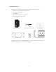
Package Contents Please refer to the package content list below to verify them against the checklist. • SISTM10xx-162-LRx Managed Industrial Switch • DC Jack 2.0/150mm RoHS • User manual CD • DIN-Rail Bracket (attached on the switch) • One wall mount plate and six screws SISTM10xx-162-LRx Wall Mount Plate DC Jack 2.0/150mm RoHS Screws User Manual CD DIN-Rail Bracket (installed) Compare the contents of the industrial switch with the standard checklist above.
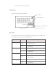
Hardware Description In this paragraph, it will describe the Industrial switch’s hardware spec, port, cabling information, and wiring installation. Physical Dimension 54mm (w) x 135mm (h) x 105mm (d) Front Panel The Front Panel of the SISTM10xx-162-LRx Managed Industrial Switch is shown below: Reset Button The reset button provides user a quick and easy way to restart and set the configuration back to default value.
set all configurations back to default setting Bottom View The bottom view of the switch is shown below: Grounding Screw 6-position terminal block Primary power input terminals (2) Secondary power input Contact relay output terminals (2) DIP-switch The switch provides the 9 DIP-switch for configuring the relay alarm operation mode and the master ring operation mode. The default value of Dipswitch is OFF.
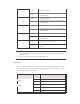
OFF Disable port Alarm 5 Enable port Alarm. If the port’s link fails, the fault ON LED will light up OFF 6 Disable port Alarm Enable port Alarm. If the port’s link fails, the fault ON LED will light up OFF 7 Disable port Alarm Enable port Alarm. If the port’s link fails, the fault ON LED will light up OFF 8 Disable port Alarm Enable port Alarm.
Off Yellow No power inputs Power failure or UTP port failure or Fiber port failure Fault Off Green No Power failure or UTP port failure or Fiber port failure occurs The industrial switch is the master of X-Ring group R.M.
All ports on this industrial switch support automatic MDI/MDI-X operation, user can use straightthrough cables (See figure below) for all network connections to PCs or servers, or to other switches or hubs. In straight-through cable, pins 1, 2, 3, and 6, at one end of the cable, are connected straight through to pins 1, 2, 3 and 6 at the other end of the cable. The table below shows the 10BASET/100BASE-TX MDI and MDI-X port pin outs.
ATTENTION This is a Class 1 Laser/LED product. Don’t stare into the Laser/LED Beam. Cabling • Using four twisted-pair, Category 5 cabling for RJ-45 port connection. The cable between the converter and the link partner (switch, hub, workstation, etc.) must be less than 100 meters (328 ft.) long. • Fiber segment using single-mode connector type must use 9/125 um single-mode fiber cable. • Fiber segment using multi-mode connector type must use 50 or 62.
Wiring the Fault Alarm Contact The fault alarm contact is in the middle of terminal block connector as below figure shows. By inserting the wires and set the DIP switch at “ON” status, it will detect the fault status which the power is failure or port link failure and form an open circuit. And, application example for the fault alarm contact as below: 1A@24V Insert the wires into the fault alarm contact [NOTE] The wire range of terminal block is from 12~ 24 AWG.
Mounting Installation DIN-Rail Mounting The DIN-Rail is screwed on the industrial switch when out of factory. 1. First, insert the top of DIN-Rail into the track. 2. Then, lightly push the DIN-Rail into the track.
3. Check the DIN-Rail is tightly on the track. 4. To remove the industrial switch from the track, reverse steps above. Wall Mount Plate Mounting Follow the below steps to mount the industrial switch with wall mount plate. 1. Remove the DIN-Rail from the industrial switch; loose the screws to remove the DIN-Rail. 2. Place the wall mount plate on the rear panel of the industrial switch. 3. Use the screws to screw the wall mount plate on the industrial switch. 4.
Hardware Installation Installation Steps 1. Unpacking the Industrial switch 2. Check the DIN-Rail is screwed on the Industrial switch. If the DIN-Rail is not screwed on the Industrial switch. Please refer to DIN-Rail Mounting section for DIN-Rail installation. If user want to wall mount the Industrial switch, then please refer to Wall Mount Plate Mounting section for wall mount plate installation. 3.
Network Application This chapter provides some sample applications to help user to have more actual idea of industrial switch function application.
X-Ring Application The industrial switch supports the X-Ring protocol that can help the network system to recovery from network connection failure within 300ms or less, and make the network system more reliable. The XRing algorithm is like as spanning tree protocol (STP) algorithm but it has faster recovery time than STP. The following figure is a sample X-Ring application.
Coupling Ring Application In the network, it may have more than one X-Ring group. By using the coupling ring function can connect each X-Ring for the redundant backup. It can ensure the transmissions between two ring groups will no failure. The following figure is a sample of coupling ring application. Dual Homing Application Dual Homing function is to prevent a lost connection between X-Ring group and upper level/core switch.
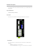
Web-Based Management About Web-based Management On CPU board of the switch there is an embedded HTML web site residing in flash memory, which offers advanced management features and allow users to manage the switch from anywhere on the network through a standard browser such as Microsoft Internet Explorer. The Web-Based Management supports Internet Explorer 6.0. And, it is applied for Java Applets for reducing network bandwidth consumption, enhance access speed and present an easy viewing screen.
Function Menu Bar Home Interface Panel Figure Display Configuration Display Screen Port status View every port status that depended on user’s setting and the negotiation result • Port: The port number • Type: The speed mode, ex: 100TX = 100Mbps • Link: “Down” means “No Link”. “UP” is for “Link” • State: Display port statuses “disable” or “enable”. “Unlink” will be treated as “off” • Negotiation: Display the auto negotiation mode: auto/force. “Config” means the value that user configured.
Single Port Information Click the port on the Panel figure on the web interface directly. Then, the single port information window will show up and display the port current information.
Port Control Change the port status • Select the port by scroll the Port column • State: Disable or enable control of this port • Negotiation: Set auto negotiation mode is Auto, Nway (specify the speed/duplex on this port and enable auto-negotiation), or Force • Speed: Set the speed of the port • Duplex: Set full-duplex or half-duplex mode of the port • Flow control: Set flow control function is Symmetric or Asymmetric in Full Duplex mode.
• Hardware version: Display the switch hardware version • MAC Address: Display the unique hardware address assigned by manufacturer (default) Switch settings interface [NOTE] Remember to execute the “Save Configuration” action, otherwise the new configuration will lose when switch power off. Port Mirroring The Port mirroring is a method for monitor traffic in switched networks. Traffic through ports can be monitored by one specific port.
Port Mirroring interface [NOTE] 1. Select the monitor mode as disable to disable the mirroring 2. Remember to execute the “Save Configuration” action, otherwise the new configuration will lose when switch power off. VLAN configuration A Virtual LAN (VLAN) is a logical network grouping that limits the broadcast domain, which would, allow you to isolate network traffic so only the members of the VLAN will receive traffic from the same members of VLAN.
VLAN Configuration interface Port-based VLAN Packets can go among only members of the same VLAN group. Note all unselected ports are treated as belonging to another single VLAN. If the port-based VLAN enabled, the VLAN-tagging is ignored.
• Click Add to add a new VLAN group(The maximum VLAN group is up to 64 VLAN groups) • Entering the VLAN name, group ID and grouping the members of VLAN group • And then, click Apply VLAN—PortBase Add interface • The VLAN group will list • To view the another VLAN groups, click • To delete unwanted VLAN, click • To modify existing VLAN group, press Next Page Delete button Edit button [NOTE] Remember to execute the “Save Configuration” action, otherwise the new configuration will lose when
802.1Q VLAN Tagged-based VLAN is an IEEE 802.1Q specification standard which it allows to create a VLAN across devices from different switch venders. IEEE 802.1Q VLAN uses a technique to insert a “tag” into the Ethernet frames. Tag contains a VLAN Identifier (VID) that indicates the VLAN numbers. All ports on the switch belong to default VLAN, VID is 1. The default VLAN can’t be deleting. The maximum VLAN group is up to 64 VLAN groups. 802.
• Grouping the ports and click Add button 802.1q VLAN –Add interface • And then, click Next then follow interface as below.
Apply Click to set the outgoing frames are VLAN-Tagged frames or untagged Tag: Outgoing frames with VLAN-Tagged Untag: Outgoing frames without VLAN-Tagged Port VLAN ID • Configure port VID settings • Port VLAN ID: Enter the port VLAN ID • And then, click Apply • To reset back to default value, click Default button 802.1q VLAN – Port VLAN ID interface [NOTE] Remember to execute the “Save Configuration” action, otherwise the new configuration will lose when switch power off.
Alert There are three kinds of alert – e-mail, event, and power alarm for user to configure. Email Alert Configuration When the specific events occur, the system will send the alert to the email account that is assigned by user. User can set up the mail server IP, mail account, and forwarded email account for receiving the event alert.
Event Configuration The selected events that occur will send out the alert to the assigned SMTP server. Also, user can select port events for alerting. • System event selection: 4 selections – Device cold start, Power status, SNMP Authentication Failure, and X-Ring topology changes. Mark the checkbox to select the event.
Power Alarm Configuration Power alarm function enables the Relay alarm action. Without enabling power alarm function, the Relay alarm action will not work even the Relay alarm is set. • Mark the check box and click Apply button Power Alarm interface IP Configuration User can configure the IP Settings and DHCP client function • DHCP Client: To enable or disable the DHCP client function.
IP configuration interface SNTP Configuration User can configure the SNTP (Simple Network Time Protocol) settings. The SNTP allows user to synchronize switch clocks in the Internet. • • SNTP Client: To enable or disable SNTP function to get the time from the SNTP server Daylight Saving Time: To enable or disable daylight saving time function. When daylight saving time is enabling, user need to configure the daylight saving time period • UTC Timezone: Set the switch location time zone.
MEWT - Middle European Winter SWT - Swedish Winter EET - Eastern European, USSR Zone 1 +2 hours 2 pm BT - Baghdad, USSR Zone 2 +3 hours 3 pm ZP4 - USSR Zone 3 +4 hours 4 pm ZP5 - USSR Zone 4 +5 hours 5 pm ZP6 - USSR Zone 5 +6 hours 6 pm WAST - West Australian Standard +7 hours 7 pm CCT - China Coast, USSR Zone 7 +8 hours 8 pm JST - Japan Standard, USSR Zone 8 +9 hours 9 pm +10 hours 10 pm +12 hours Midnight EAST - East Australian Standard GST Guam Standard, USSR Zone 9 IDLE - Int
IP Security IP security function allows user to assign 10 specific IP addresses that have permission to access the switch through the web browser for the securing switch management. • • Enable the IP Security: Mark the check box to enable the IP security function Security IP 1 ~ 10: Assign up to 10 specific IP address.
System Configuration • User can view spanning tree information about the Root Bridge • User can modify RSTP state. After modification, click Apply button RSTP mode: user must enable or disable RSTP function before configure the related parameters Priority (0-61440): a value used to identify the root bridge. The bridge with the lowest value has the highest priority and is selected as the root. If the value changes, user must reboot the switch.
RSTP– System Configuration Interface Per Port Configuration Configure path cost and priority of every port • Select the port in Port column • Path Cost: The cost of the path to the other bridge from this transmitting bridge at the specified port. Enter a number 1 through 200000000 • Priority: Decide which port should be blocked by priority in LAN. Enter a number 0 through 240.
RSTP – Per Port Configuration interface X-Ring X-Ring provides a faster redundant recovery than Spanning Tree topology. The action is similar with STP or RSTP, but the algorithms not the same. In the X-Ring topology, every switch should enable X-Ring function and assign two member ports in the ring. Only one switch in the X-Ring group would be set as a backup switch that one of two member ports would be blocking, called backup port, and another port is called working port.
The system also supports the coupling ring that can connect 2 or more X-Ring group for the redundant backup function and dual homing function that prevent connection lose between X-Ring group and upper level/core switch. • Enable X-Ring: To enable the X-Ring function. Marking the check box to enable the X-Ring function. • st nd 1 &2 Working Ports: Assign two ports as the member ports. One port will be working port and one port will be the backup port.
QoS Configuration Configure Qos setting of the every port • Oos Policy: Select the Qos policy rule Using the 8,4,2,1 weight fair queue scheme: The switch will follow 8:4:2:1 rate to process priority queue from Hi to lowest queue.
QoS configuration Interface IGMP The Internet Group Management Protocol (IGMP) is an internal protocol of the Internet Protocol (IP) suite. IP manages multicast traffic by using switches, routers, and hosts that support IGMP. Enabling IGMP allows the ports to detect IGMP queries and report packets and manage IP multicast traffic through the switch.
Message Description A message sent from the querier (IGMP router or switch) asking Query for a response from each host belonging to the multicast group. A message sent by a host to the querier to indicate that the host Report wants to be or is a member of a given group indicated in the report message. A message sent by a host to the querier to indicate that the host Leave Group has quit to be a member of a specific multicast group. User can enable IGMP protocol and IGMP Query function in here.
4. And then, click Apply Security Manager interface [NOTE] Remember to execute the “Save Configuration” action, otherwise the new configuration will lose when switch power off. SNMP Configuration The SNMP is a Protocol that governs the transfer of information between management and agent. The switch supports SNMP V1. User can define management stations as trap managers and to enter SNMP community strings. User also can define a name, location, and contact person for the switch.
System Options • Name: Enter a name for the switch • Location: Enter the switch physical location • Contact: Enter the name of contact person or organization Community strings Serve as a password. • Strings: Key in the name of string • RO: Read only. Enables requests accompanied by this string to display MIB-object information • RW: Read write.
TFTP Restore Configuration interface TFTP Backup Configuration User can save current flash ROM value from the industrial switch to the TFTP server, then go to the TFTP restore configuration page to restore the image value back to the industrial switch.
• And then, click Apply TFTP Update Firmware interface Factory Default Reset Switch to default configuration. Except the IP address, subnet mask, default gateway, username, and password will remain as user configured.
Save Configuration Save the industrial switch configuration to the flash memory. Power off the industrial switch without the saving, all changed configuration will lost. • Click the Save Flash button the save the configuration Save Configuration Interface Rate Control Set up every port’s bandwidth rate and packet limitation type • Limit Packet type: Select the packet type that wants to filter.
Rate Control Interface [NOTE] 1. Remember to execute the “Save Configuration” action, otherwise the new configuration will lose when switch power off. 2. Qos and Rate control cannot be existed at the same. System Log Set up system log events and view the system log events System Log Configuration Reload • Click • To clear the log events, click • If log event list more that one page, drag down the list to switch to different page.
System Log Configuration interface Event Configuration User can select the system log events. When selected events occur, the system will send out the log information. Also, per port log events can be selected. • System event selection: 4 selections – Device cold start, Power status, SNMP Authentication Failure, and X-Ring topology change. Mark the checkbox to select the event.
• After selected, click Apply Event Configuration interface 47
Troubles shooting • Verify that is using the right power cord/adapter (DC 12-48V), please don’t use the power adapter with DC output bigger than 48V, or it will burn this converter down. • Select the proper UTP cable to construct user network. Please check that is using the right cable. use unshielded twisted-pair (UTP) or shield twisted-pair ( STP ) cable for RJ-45 connections: 100 Category 3, 4 or 5 cable for 10Mbps connections or 100 Category 5 cable for 100Mbps connections.
Technical Specification IEEE 802.3 10Base-T Ethernet IEEE 802.3u 100Base-TX and 100Base-FX Fast Ethernet Standard IEEE802.3x Flow Control and Back-pressure IEEE802.1d spanning tree / IEEE802.1w rapid spanning tree IEEE802.1p class of service IEEE802.
4 types of packet filter rule with different packet combination: All of packet Packet filter Broadcast/ multicast/ unknown unicast packet Broadcast/ multicast packet Broadcast packet only MAC address 2K MAC address table Memory Buffer 1Mbits LED Per unit: Power (Green), Power 1 (Green), Power 2 (Green), Per port: Link/Activity (Green), Full duplex/Collision (Yellow) Fault (Yellow), Master (Green) 10Base-T: 2-pair UTP/STP Cat.
Spanning tree IGMP SMTP SNTP Management IP security Port mirror Firmware update IEEE802.1d spanning tree IEEE802.1w rapid spanning tree. IGMP v1 and Query mode Up to 256 groups.
Case Dimension IP-30, 54 mm (W) x 135 mm (H) x 105mm (D) FCC Class A, CE EN61000-4-2 (ESD), CE EN61000-4-3 (RS), CE EN-61000-4-4 (EFT), EMI CE EN61000-4-5 (Surge), CE EN61000-4-6 (CS), CE EN61000-4-8, CE EN61000-4-11, CE EN61000-4-12, CE EN61000-6-2, CE EN61000-6-4 Safety UL, cUL, CE/EN60950-1 IEC60068-2-32 (Free fall) Stability testing IEC60068-2-27 (Shock) IEC60068-2-6 (Vibration) 52