8 10/100TX + 2 10/100/1000T/Mini-GBIC Combo with 8 PoE Injector Industrial Switch User Manual SISPM1040-182D Version 1.
Transition Networks SISPM1040-182D Revision History Document Date Revision Initials 1.00 Oct 31, 2008 First release A.E.F 1.01 Oct 21, 2009 Corrections A.E.
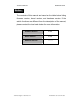
Transition Networks SISPM1040-182D Notice The contents of this manual are based on the table below listing firmware version, kernel version, and hardware version. If the switch functions are different from the description of the manual, please contact the local sale dealer for more information. Firmware Version V1.00 Kernel Version V1.
Transition Networks SISPM1040-182D FCC Warning This Equipment has been tested and found to comply with the limits for a Class-A digital device, pursuant to Part 15 of the FCC rules. These limits are designed to provide reasonable protection against harmful interference in a residential installation. This equipment generates, uses, and can radiate radio frequency energy. It may cause harmful interference to radio communications if the equipment is not installed and used in accordance with the instructions.
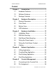
Transition Networks SISPM1040-182D Content Chapter 1 Introduction......................................... 1 1.1 Hardware Features...................................... 1 1.2 Software Features ....................................... 5 1.3 Package Contents ....................................... 8 Chapter 2 Hardware Description ........................ 9 2.1 Physical Dimension ..................................... 9 2.2 Front Panel.................................................. 9 2.
Transition Networks SISPM1040-182D-LR 5.3 Login in the Console Interface................... 30 5.4 CLI Management....................................... 32 5.5 Commands Level ...................................... 32 Chapter 6 Web-Based Management................. 34 6.1 About Web-based Management................ 34 6.2 Preparing for Web Management ............... 34 6.3 System Login............................................. 35 6.4 System Information ...................................
Transition Networks SISPM1040-182D-LR 6.22 IGMP Configuration................................ 100 6.23 X-Ring..................................................... 102 6.24 LLDP Configuration ................................ 105 6.25 Security—802.1X/Radius Configuration. 106 6.26 MAC Address Table ............................... 110 6.27 Power over Ethernet............................... 115 6.28 Factory Default ....................................... 117 6.29 Save Configuration.............
Transition Networks SISPM1040-182D-LR TFTP Commands Set .......................................... 145 SystemLog, SMTP and Event Commands Set .... 145 SNTP Commands Set.......................................... 147 X-ring Commands Set..........................................
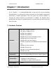
Transition Networks SISPM1040-182D Chapter 1 Introduction The 8 10/100TX + 2 10/100/1000T/Mini-GBIC Combo w/8 PoE Injectors Managed Industrial Switch is a cost-effective solution and meets the high reliability requirements demanded by industrial applications. Fiber can extend the connection distance to increases the network elasticity and performance. In addition, the industrial switch provides the PoE function for Powered Devices to receive power as well as data over the RJ-45 cable. 1.
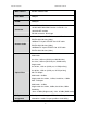
Transition Networks SISPM1040-182D-LR MAC Address 8K MAC address table Flash ROM 4Mbytes DRAM 32Mbytes 10/100TX: 8 x RJ-45 Connector 10/100/1000T/ Mini-GBIC Combo: 2 x RJ-45 + 2 x 100/1000 SFP sockets RS-232 connector: RJ-45 type 10Base-T: 2-pair UTP/STP Cat. 3, 4, 5/ 5E cable EIA/TIA-568 100-ohm (100m) Network Cable 100Base-TX: 2-pair UTP/STP Cat. 5/ 5E cable EIA/TIA-568 100-ohm (100m) 1000Base-TX: 2-pair UTP/STP Cat.
Transition Networks SISPM1040-182D-LR Positive (VCC+): RJ-45 pin 1,2. Negative (VCC-): RJ-45 pin 3,6.
Transition Networks Stability Testing SISPM1040-182D-LR IEC60068-2-32 (Free fall), IEC60068-2-27 (Shock), IEC60068-2-6 (Vibration) Technical Support: 1-800-260-1312 International: 00-1-952-941-7600 4
Transition Networks SISPM1040-182D-LR 1.2 Software Features Management SNMP v1 v2c, v3/ Web/Telnet/CLI RFC 1215 Trap, RFC1213 MIBII, RFC 1157 SNMP MIB, RFC 1493 SNMP MIB Bridge MIB, RFC 2674 VLAN MIB, RFC 1643 , RFC 1757, RSTP MIB, Private MIB, LLDP MIB Port Based VLAN VLAN IEEE 802.1Q Tag VLAN (256 entries)/ VLAN ID (Up to 4K, VLAN ID can be assigned from 1 to 4096.
Transition Networks Port Mirror IGMP SISPM1040-182D-LR Supports 3 mirroring types: “RX, TX and Both packet”. Supports IGMP snooping v1,v2 256 multicast groups and IGMP query Supports 10 IP addresses that have permission to access IP Security the switch management and to prevent unauthorized intruder. Login Security Supports IEEE802.
Transition Networks SISPM1040-182D-LR 4. Authorization fail 5. PD disconnect trap-PoE port event DHCP DNS Provides DHCP Client/ DHCP Server/ Port and IP Binding Provides DNS client feature and supports Primary and Secondary DNS server SNTP Supports SNTP to synchronize system clock in Internet Firmware Update Supports TFTP firmware update, TFTP backup and restore.
Transition Networks SISPM1040-182D-LR 1.3 Package Contents Please refer to the package content list below to verify them against the checklist. 8 10/100TX + 2 10/100/1000T/Mini-GBIC Combo w/8 PoE Injectors Managed Industrial Switch x 1 User manual x 1 Pluggable Terminal Block x 1 Mounting plate x 2 RJ-45 to DB9-Female cable x 1 Compare the contents of the industrial switch with the standard checklist above. If any item is damaged or missing, please contact the local dealer for service.
Transition Networks SISPM1040-182D Chapter 2 Hardware Description This chapter will describe the Industrial switch’s hardware spec, port, cabling information, and wiring installation. 2.1 Physical Dimension 8 10/100TX w/ X-Ring Managed Industrial Switch dimension (W x D x H) is 72mm x 105mm x 152mm 2.
Transition Networks SISPM1040-182D-LR 2.3 Bottom View The bottom panel of the 8 10/100TX w/ X-Ring Managed Industrial Switch has one terminal block connector for two (2) DC power inputs and one fault alarm.
Transition Networks SISPM1040-182D 2.4 LED Indicators The diagnostic LEDs that provide real-time status information are located on the front panel of the industrial switch. The following table provides the description of the LED status and their meanings. LED Color PWR Green Status On The switch unit is powered on Off No power On R.M.
Transition Networks SISPM1040-182D-LR On The SFP port is linking Link/Active (P9, P10 Green Blinks SFP) Green Amber No device attached On A network device is detected. Blinking from the TX device. No device attached The port is operating in full-duplex mode. Blinking Collision of Packets occurs. Green P8) The port is transmitting or receiving packets On Off FWD (P1 ~ from the TX device.
Transition Networks SISPM1040-182D Chapter 3 Hardware Installation This chapter describes how to physically install the 8 10/100TX w/ X-Ring Managed Industrial Switch. 3.1 Installation Steps 1. Unpack the Industrial switch 2. Check if the DIN-Rail is screwed on the Industrial switch or not. If the DIN-Rail is not screwed on the Industrial switch, please refer to DIN-Rail Mounting section for DINRail installation.
Transition Networks SISPM1040-182D-LR 3.2 DIN-Rail Mounting The DIN-Rail is factory installed. If the DIN-Rail is not screwed on the industrial switch, please see the following pictures. Follow the steps below to hang the industrial switch.
Transition Networks SISPM1040-182D 1. First, insert the top of DIN-Rail into the track. 2. Then, lightly push the DIN-Rail into the track. 3. Verify the DIN-Rail is tightened. 4. To remove the industrial switch from the track, reverse above steps.
Transition Networks SISPM1040-182D 3.3 Wall Mount Plate Mounting Follow the steps below to mount the industrial switch with wall mount plate. 1. Remove the DIN-Rail from the industrial switch; loose the screws to remove the DINRail. 2. Place the wall mount plate on the rear panel of the industrial switch. 3. Use the screws to screw the wall mount plate on the industrial switch. 4. Use the hook holes at the corners of the wall mount plate to hang the industrial switch on the wall. 5.
Transition Networks SISPM1040-182D 3.4 Wiring the Power Inputs Please follow the steps below to insert the power wire. 1. Insert AC or DC power wires into the contacts 1 and 2 for power 1, or 5 and 6 for power 2. 2. Tighten the wire-clamp screws. [NOTE] The wire gauge should be in the range 12 ~ 24 AWG.
Transition Networks SISPM1040-182D 3.5 Wiring the Fault Alarm Contact The fault alarm contacts are in the middle of the terminal block connector as the picture below shows. If configured the switch will detect power failure, or port link failure (available for managed model) and then form an open circuit. The following illustration shows an application example for wiring the fault alarm contacts.
Transition Networks SISPM1040-182D 3.6 Cabling Use four twisted-pair, Category 5e or above cabling for RJ-45 port connection. The cable between the switch and the link partner (switch, hub, workstation, etc.) must be less than 100 meters (328 ft.) long. Fiber segment using single-mode connector type must use 9/125 μm single-mode fiber cable. User can connect two devices in the distance up to 30km. Fiber segment using multi-mode connector type must use 50 or 62.5/125 μm multimode fiber cable.
Transition Networks SISPM1040-182D-LR To connect the transceiver and LC cable, please follow the steps shown below: First, insert the transceiver into the SFP module. Notice that the triangle mark is the bottom of the module. Transceiver to the SFP module Transceiver Inserted Second, insert the fiber cable of LC connector into the transceiver.
Transition Networks SISPM1040-182D-LR LC connector to the transceiver Technical Support: 1-800-260-1312 International: 00-1-952-941-7600 21
Transition Networks SISPM1040-182D-LR To remove the LC connector from the transceiver, please follow the steps shown below: First, press the upper side of the LC connector to release from the transceiver and pull it out. Remove LC connector Second, push down the metal loop and pull the transceiver out by the plastic handle.
Transition Networks SISPM1040-182D Chapter 4 Network Application This chapter illustrates some example applications.
Transition Networks SISPM1040-182D-LR The illustration below shows an example power over Ethernet application.
Transition Networks SISPM1040-182D 4.1 X-Ring Application The industrial switch supports the X-Ring protocol that can help the network recover from connection failure within 20ms or less, and make the network system more reliable. The X-Ring algorithm is similar to spanning tree protocol (STP) algorithm but its recovery time is faster than STP. The following figure is a sample X-Ring application.
Transition Networks SISPM1040-182D 4.2 Coupling Ring Application A network may have more than one X-Ring group. The coupling ring function can connect each X-Ring for redundant backup. It can ensure transmissions between two ring groups do not fail. The following figure illustrates a coupling ring application.
Transition Networks SISPM1040-182D 4.3 Dual Homing Application The Dual Homing function prevents lost connection between an X-Ring group and an upper level/core switch. Assign two ports to be the Dual Homing ports in the X-Ring group. The Dual Homing function only works when the X-Ring function is active. Each XRing group only has one Dual Homing port. [NOTE] In Dual Homing application architecture, the upper level switches need to enable the Rapid Spanning Tree protocol.
Transition Networks SISPM1040-182D 4.4 Dual Ring Application Dual ring is an advanced function that supports backup connection to ensure redundant transmission. If the connection fails, the system will recover from fwithin 20 milliseconds. Apart from that, Dual Ring only needs one unit (and only the one located in the middle) to be configured as the Ring Master switch to deploy the dual ring.
Transition Networks SISPM1040-182D Chapter 5 Console Management 5.1 Connecting to the Console Port The supplied cable has an RS-232 connector on one end and an RJ-45 connector on the other end. Attach the RS-232 connector to a PC or terminal and the other end of RJ-45 connector to the console port of the switch. The connected terminal or PC must support the terminal emulation program. 5.
Transition Networks SISPM1040-182D-LR 5.3 Login in the Console Interface When the connection between the Switch and the PC is ready, turn on the PC and run a terminal emulation program or Hyper Terminal and configure its communication parameters to match the following default characteristics of the console port: Baud Rate: 9600 bps Data Bits: 8 Parity: none Stop Bit: 1 Flow control: None The settings of communication parameters After changing the parameter settings, click ‘OK’.
Transition Networks SISPM1040-182D-LR Console login interface Technical Support: 1-800-260-1312 International: 00-1-952-941-7600 31
Transition Networks SISPM1040-182D 5.4 CLI Management The switch supports console management—CLI commands. After you log in to the system, you will see a command prompt. To enter CLI management interface, type “enable”. CLI command interface The following table lists the CLI commands and their description. 5.5 Commands Level Modes Access Method Prompt Exit Method About This Mode1 The user commands available at the user level are a subset of Begin a User EXEC session with switch> your switch.
Transition Networks SISPM1040-182D-LR Enter the configure Global command switch Configuration while in (config)# privileged EXEC mode. To exit to Use this mode to privileged configure those EXEC parameters that are mode, enter going to be applied to exit or end your switch. Enter the vlan VLAN database database command while in To exit to switch user EXEC (vlan)# mode, enter exit. privileged Use this mode to configure VLANspecific parameters. EXEC mode.
Transition Networks SISPM1040-182D Chapter 6 Web-Based Management This section introduces the configuration and functions of the Web-Based management. 6.1 About Web-based Management There is an embedded HTML web server residing in flash memory in the switch. This offers advanced management features and allows users to manage the switch from anywhere on the network through a standard web browser such as Microsoft Internet Explorer. The Web-Based Management supports Internet Explorer 6.0 or later version.
Transition Networks SISPM1040-182D-LR 6.3 System Login 1. Launch the Internet Explorer on the PC 2. Key in “http:// “+” the IP address of the switch”, and then Press “Enter”. 3. The login screen will appear right after 4. Key in the user name and password. The default user name and password are ‘root’. 5. Press Enter or click the OK button. Then the home screen of the Web-based management appears.
Transition Networks SISPM1040-182D-LR 6.4 System Information Users can assign the system name, description, location and contact personnel to identify the switch. The version table below is a read-only field to show the basic information of the switch. System Name: Assign the system name of the switch (The maximum length is 64 bytes) System Description: Describes the switch. System Location: Assign the switch physical location (The maximum length is 64 bytes).
Transition Networks SISPM1040-182D 6.5 IP Configuration The switch is a network device which needs to be assigned an IP address for being identified on the network. Users have to decide a means of assigning IP address to the switch. DHCP Client: Enable or disable the DHCP client function. When DHCP client function is enabled, the switch will be assigned an IP address from the network DHCP server. The default IP address will be replaced by the assigned IP address on DHCP server.
Transition Networks SISPM1040-182D-LR IP configuration interface Technical Support: 1-800-260-1312 International: 00-1-952-941-7600 38
Transition Networks SISPM1040-182D 6.6 DHCP Server DHCP is the abbreviation of Dynamic Host Configuration Protocol that is a protocol for assigning dynamic IP addresses to devices on a network. With dynamic addressing, a device can have a different IP address every time it connects to the network. In some systems, the device's IP address can even change while it is still connected. DHCP also supports a mix of static and dynamic IP addresses.
Transition Networks SISPM1040-182D 6.6.1 System configuration DHCP Server: Enable or Disable the DHCP Server function. Enable—the switch will be the DHCP server on your local network. Low IP Address: Type in an IP address. Low IP address is the beginning of the dynamic IP range. For example, dynamic IP is in the range between 192.168.1.100 ~ 192.168.1.200. In contrast, 192.168.1.100 is the Low IP address. High IP Address: Type in an IP address.
Transition Networks SISPM1040-182D 6.6.2 Client Entries When the DHCP server function is enabled, the system will collect the DHCP client information including the assigned IP address, the MAC address of the client device, the IP assigning type, status and lease time.
Transition Networks SISPM1040-182D 6.6.3 Port and IP Bindings Assign the dynamic IP address bound with the port to the connected client. The user is allowed to fill each port column with one particular IP address. When the device is connecting to the port and asks for IP assigning, the system will assign the IP address bound with the port.
Transition Networks SISPM1040-182D 6.7 TFTP TFTP allows the user to update the switch firmware via the Trivial File Transfer Protocol (TFTP) server. Before updating, make sure the TFTP server is ready and the firmware image is located on the TFTP server. 6.7.1 Update Firmware TFTP Server IP Address: Type in your TFTP server IP. Firmware File Name: Type in the name of the firmware image file to be updated. Click Apply .
Transition Networks SISPM1040-182D 6.7.2 Restore Configuration You can restore a previous backup configuration from the TFTP server to recover the settings. Before doing so, you must locate the image file on the TFTP server. TFTP Server IP Address: Type in the TFTP server IP. Restore File Name: Type in the correct file name for restoring configuration. Click Apply .
Transition Networks SISPM1040-182D 6.7.3 Backup Configuration You can back up the current configuration from flash ROM to the TFTP server for the purpose of recovering the configuration later. It helps you save time. TFTP Server IP Address: Type in the TFTP server IP. Backup File Name: Type in the file name. Click Apply .
Transition Networks SISPM1040-182D 6.8 System Event Log This page allows the user to decide whether to send the system event log, and select the mode which the system event log will be sent to client only, server only, or both client and server. What kind of event log will be issued to the client/server depends on the selection on the Event Configuration tab.
Transition Networks SISPM1040-182D-LR Syslog Configuration interface Technical Support: 1-800-260-1312 International: 00-1-952-941-7600 47
Transition Networks SISPM1040-182D 6.8.2 System Event Log—SMTP Configuration Simple Mail Transfer Protocol (SMTP) is the standard for email transmissions across the network. You can configure the SMTP server IP, mail subject, sender, mail account, password, and the recipient email addresses which the e-mail alert will send to. There are also five types of event—Device Cold Start, Device Warm Start, Authentication Failure, X-Ring Topology Change, and Port Event—available to be issued as the e-mail alert.
Transition Networks SISPM1040-182D-LR SMTP Configuration interface Technical Support: 1-800-260-1312 International: 00-1-952-941-7600 49
Transition Networks SISPM1040-182D 6.8.3 System Event Log—Event Configuration Having ticked the Syslog/SMTP checkboxes, the event log/email alert will be sent to the system log server and the SMTP server respectively. Also, Port event log/alert (link up, link down, and both) can be sent to the system log server/SMTP server respectively by setting the trigger condition.
Transition Networks SISPM1040-182D-LR Event Configuration interface Technical Support: 1-800-260-1312 International: 00-1-952-941-7600 51
Transition Networks SISPM1040-182D 6.9 Fault Relay Alarm The Fault Relay Alarm function provides Power Failure and Port Link Down/Broken detection. With both power input 1 and power input 2 installed and the check boxes of power 1/power 2 ticked, the FAULT LED indicator will then light up if either power failure occurs. As for the Port Link Down/Broken detection, the FAULT LED indicator will light up when the port failure occurs; the check box beside the port must be ticked first.
Transition Networks 6.10 SISPM1040-182D SNTP Configuration SNTP (Simple Network Time Protocol) is a simplified version of NTP which is an Internet protocol used to synchronize the clocks of computers to some time reference. Because time usually just advances, the time on different node stations will be different. With the communicating programs running on those devices, it would cause time to jump forward and back, a non-desirable effect.
Transition Networks EST - Eastern Standard SISPM1040-182D-LR -5 hours 7 am -6 hours 6 am -7 hours 5 am -8 hours 4 am -9 hours 3 am -10 hours 2 am -11 hours 1 am +1 hour 1 pm +2 hours 2 pm +3 hours 3 pm ZP4 - USSR Zone 3 +4 hours 4 pm ZP5 - USSR Zone 4 +5 hours 5 pm ZP6 - USSR Zone 5 +6 hours 6 pm +7 hours 7 pm CDT - Central Daylight CST - Central Standard MDT - Mountain Daylight MST - Mountain Standard PDT - Pacific Daylight PST - Pacific S
Transition Networks SISPM1040-182D-LR CCT - China Coast, USSR Zone 7 JST - Japan Standard, USSR Zone 8 +8 hours 8 pm +9 hours 9 pm +10 hours 10 pm +12 hours Midnight EAST - East Australian Standard GST Guam Standard, USSR Zone 9 IDLE - International Date Line NZST - New Zealand Standard NZT - New Zealand SNTP Sever URL: Set the SNTP server IP address. You can assign a local network time server IP address or an internet time server IP address.
Transition Networks SISPM1040-182D-LR SNTP Configuration interface Technical Support: 1-800-260-1312 International: 00-1-952-941-7600 56
Transition Networks 6.11 SISPM1040-182D IP Security IP security allows the user to assign 10 specific IP addresses that have permission to manage the switch through the http and telnet services. The purpose of providing limited IP addresses permission is to allow only the authorized personnel/device access to management tasks on the switch.
Transition Networks SISPM1040-182D-LR IP Security interface Technical Support: 1-800-260-1312 International: 00-1-952-941-7600 58
Transition Networks 6.12 SISPM1040-182D User Authentication Change web management login user name and password for the management security issue.
Transition Networks 6.13 SISPM1040-182D Port Statistics The following chart provides the current statistic information which displays the real-time packet transfer status for each port. The user might use the information to plan and implement the network, or check and find problems when collisions or heavy traffic occurs. Port: The port number. Type: Displays the current speed of connection to the port. Link: The status of linking—‘Up’ or ‘Down’. State: It’s set by Port Control.
Transition Networks SISPM1040-182D-LR Port Statistics interface Technical Support: 1-800-260-1312 International: 00-1-952-941-7600 61
Transition Networks 6.14 SISPM1040-182D Port Control In Port control you can configure the settings of each port to control the connection parameters, and the status of each port is listed beneath. Port: Use the scroll bar and click on the port number to choose the port to be configured. State: Current port state. The port can be set to disable or enable mode. If the port state is set as ‘Disable’, it will not receive or transmit any packet. Negotiation: Auto and Force.
Transition Networks SISPM1040-182D-LR Port Control interface Technical Support: 1-800-260-1312 International: 00-1-952-941-7600 63
Transition Networks 6.15 SISPM1040-182D Port Trunk Port trunking is the combination of several ports or network cables to expand the connection speed beyond the limits of any one single port or network cable. Link Aggregation Control Protocol (LACP), which is a protocol running on layer 2, provides a standardized means in accordance with IEEE 802.3ad to bundle several physical ports together to form a single logical channel.
Transition Networks SISPM1040-182D-LR ports to be aggregated in a trunk group. Click Add and the ports focused in the right side will be shifted to the left side. To remove unwanted ports, select the ports and click Remove . When LACP enabled, you can configure LACP Active/Passive status for each port on the State Activity tab. Click Use Delete to delete Trunk Group. Select the Group ID and click Delete . Apply .
Transition Networks SISPM1040-182D 6.15.2 Aggregator Information z LACP disabled Having set up the aggregator setting with LACP disabled, you will see the local static trunk group information on the tab of Aggregator Information. Assigning 2 ports to a trunk group with LACP disabled Static Trunking Group information Group Key: This is a read-only column field that displays the trunk group ID.
Transition Networks SISPM1040-182D-LR Port Member: This is a read-only column field that displays the members of this static trunk group.
Transition Networks SISPM1040-182D z LACP enabled Having set up the aggregator setting with LACP enabled, you will see the trunking group information between two switches on the tab of Aggregator Information. Switch 1 configuration 1. Set System Priority of the trunk group. The default is 1. 2. Select a trunk group ID by pull down the drop-down menu bar. 3. Enable LACP. 4.
Transition Networks SISPM1040-182D-LR Aggregation Information of Switch 1 5. Click on the tab of Aggregator Information to check the trunked group information as the illustration shown above after the two switches configured.
Transition Networks SISPM1040-182D Switch 2 configuration Switch 2 configuration interface 1. Set System Priority of the trunk group. The default is 1. 2. Select a trunk group ID by pull down the drop-down menu bar. 3. Enable LACP. 4. Include the member ports by clicking the Add button after selecting the port number and the column field of Work Ports changes automatically.
Transition Networks 5. SISPM1040-182D-LR Click on the tab of Aggregator Information to check the trunked group information as the illustration shown above after the two switches configured.
Transition Networks SISPM1040-182D 6.15.3 State Activity Having set up the LACP aggregator on the tab of Aggregator Setting, you can configure the state activity for the members of the LACP trunk group. You can tick or cancel the checkbox beside the state label. When you remove the tick mark of the port and click Apply , the port state activity will change to Passive. Active: The port automatically sends LACP protocol packets.
Transition Networks SISPM1040-182D-LR State Activity of Switch 2 Technical Support: 1-800-260-1312 International: 00-1-952-941-7600 73
Transition Networks 6.16 SISPM1040-182D Port Mirroring Port mirroring is a method for monitoring traffic in switched networks. Traffic through ports can be monitored by one specific port, which means traffic that goes in or out monitored (source) ports will be duplicated into mirror (destination) port. Destination Port: There is only one port can be selected to be destination (mirror) port for monitoring both RX and TX traffic which come from source port.
Transition Networks 6.17 SISPM1040-182D Rate Limiting You can set up every port’s bandwidth rate and frame limitation type. Ingress Limit Frame type: select the frame type that wants to filter. There are four frame types for selecting: ¾ All ¾ Broadcast/Multicast/Flooded Unicast ¾ Broadcast/Multicast ¾ Broadcast only Broadcast/Multicast/Flooded Unicast, Broadcast/Multicast and Bbroadcast only types are only for ingress frames. The egress rate only supports All type.
Transition Networks SISPM1040-182D-LR ¾ Ingress: Enter the port effective ingress rate (The default value is “0”). ¾ Egress: Enter the port effective egress rate (The default value is “0”).
Transition Networks 6.18 SISPM1040-182D VLAN configuration A Virtual LAN (VLAN) is a logical network grouping that limits the broadcast domain, which allows you to isolate network traffic. Only the members of the same VLAN will receive traffic from those of the same VLAN. Basically, creating a VLAN on a switch is the logical equivalent of reconnecting a group of network devices to another Layer 2 switch. However, all the network devices are still plugged into the same switch physically.
Transition Networks SISPM1040-182D 6.18.1 Port-based VLAN A port-based VLAN basically consists of its members—ports, which means the VLAN is created by grouping the selected ports. This method provides convenience for users to configure a simple VLAN easily without complicated steps. Packets can go among only members of the same VLAN group. Note all unselected ports are treated as belonging to another single VLAN. If the port-based VLAN is enabled, VLANtagging is ignored.
Transition Networks SISPM1040-182D-LR VLAN—Port Based Add interface Enter the group name and VLAN ID. Add the selected port number into the right field to group these members to be a VLAN group, or remove any of them listed in the right field from the VLAN. And then, click You will see the VLAN list displays. Apply to have the configuration take effect.
Transition Networks SISPM1040-182D-LR VLAN—Port Based Edit/Delete interface Use Delete Use Edit to delete the VLAN. to modify group name, VLAN ID, or add/remove the members of the existing VLAN group. [NOTE] Remember to execute the “Save Configuration” action, otherwise the new configuration will be lost when the switch power off.
Transition Networks SISPM1040-182D 6.18.2 802.1Q VLAN Virtual Local Area Network (VLAN) can be implemented on the switch to logically create different broadcast domains. When the 802.1Q VLAN function is enabled, all ports on the switch belong to default VLAN of VID 1, which means they logically are regarded as members of the same broadcast domain. The valid VLAN ID is in the range of number between 1 and 4094. The number of VLAN groups is up to 256, including the default VLAN that cannot be deleted.
Transition Networks SISPM1040-182D 802.1Q Configuration Pull down the selection item and focus on 802.1Q, then press Apply to set the VLAN Operation Mode in 802.1Q mode. Enable GVRP Protocol: GVRP (GARP VLAN Registration Protocol) is a protocol that facilitates control of virtual local area networks (VLANs) within a larger network. GVRP conforms to the IEEE 802.1Q specification, which defines a method of tagging frames with VLAN configuration data.
Transition Networks SISPM1040-182D-LR aware devices (switches). A Trunk Port, connected to the trunk link, has an understanding of tagged frame, which is used for the communication among VLANs across switches. Which frames of the specified VIDs will be forwarded depends on the values filled in the Tagged VID column field. Please insert a comma between two VIDs. Note: 1. A trunk port doesn’t insert tag into an untagged frame, and therefore the untagged VID column field is not available. 2.
Transition Networks SISPM1040-182D-LR 802.1Q VLAN interface Group Configuration Edit the existing VLAN Group. Select the VLAN group in the table list. Click Edit .
Transition Networks SISPM1040-182D-LR Group Configuration interface You can modify the VLAN group name and VLAN ID.
Transition Networks SISPM1040-182D-LR Click Apply .
Transition Networks 6.19 SISPM1040-182D Rapid Spanning Tree The Rapid Spanning Tree Protocol (RSTP) is an evolution of the Spanning Tree Protocol and provides for faster spanning tree convergence after a topology change. The system also supports STP and the system will auto-detect the connected device that is running STP or RSTP protocol. 6.19.1 RSTP System Configuration The user can view spanning tree information of Root Bridge. The user can modify RSTP state. After modification, click Apply .
Transition Networks SISPM1040-182D-LR RSTP System Configuration interface Technical Support: 1-800-260-1312 International: 00-1-952-941-7600 88
Transition Networks SISPM1040-182D 6.19.2 Port Configuration This web page provides the port configuration interface for RSTP. You can assign higher or lower priority to each port. Rapid spanning tree will have the port with the higher priority in forwarding state and block other ports to make certain that there is no loop in the LAN. Select the port in the port column field. Path Cost: The cost of the path to the other bridge from this transmitting bridge at the specified port.
Transition Networks SISPM1040-182D-LR RSTP Port Configuration interface Technical Support: 1-800-260-1312 International: 00-1-952-941-7600 90
Transition Networks 6.20 SISPM1040-182D SNMP Configuration Simple Network Management Protocol (SNMP) is the protocol developed to manage nodes (servers, workstations, routers, switches and hubs etc.) on an IP network. SNMP enables network administrators to manage network performance, find and solve network problems, and plan for network growth. Network management systems learn of problems by receiving traps or change notices from network devices implementing SNMP. 6.20.
Transition Networks SISPM1040-182D-LR SNMP System Configuration interface Technical Support: 1-800-260-1312 International: 00-1-952-941-7600 92
Transition Networks SISPM1040-182D 6.20.2 Trap Configuration A trap manager is a management station that receives the trap messages generated by the switch. If no trap manager is defined, no traps will be issued. To define a management station as a trap manager, assign an IP address, enter the SNMP community strings, and select the SNMP trap version. IP Address: Enter the IP address of the trap manager. Community: Enter the community string for the trap station.
Transition Networks SISPM1040-182D 6.20.3 SNMPV3 Configuration Configure the SNMP V3 function. Context Table Configure SNMP v3 context table. Assign the context name of context table. Click Add to add context name. Click Remove to remove unwanted context name. User Table Configure SNMP v3 user table.. User ID: set up the user name. Authentication Password: set up the authentication password. Privacy Password: set up the private password. Click Add Click to add context name.
Transition Networks SISPM1040-182D-LR SNMP V3 configuration interface Access Table Configure SNMP v3 access table. Context Prefix: set up the context name. Group Name: set up the group. Security Level: select the access level. Context Match Rule: select the context match rule. Read View Name: set up the read view. Write View Name: set up the write view.
Transition Networks SISPM1040-182D-LR Notify View Name: set up the notify view. Click Add Click to add context name. Remove to remove unwanted context name. MIBview Table Configure MIB view table. ViewName: set up the name. Sub-Oid Tree: fill the Sub OID. Type: select the type – exclude or included. Click Add Click to add context name. Remove to remove unwanted context name.
Transition Networks 6.21 SISPM1040-182D QoS Configuration Quality of Service (QoS) is the ability to provide different priority to different applications, users or data flows, or to guarantee a certain level of performance to a data flow.
Transition Networks SISPM1040-182D-LR QoS Configuration interface 6.21.2 Port-based Priority Configure the priority level for each port.
Transition Networks SISPM1040-182D-LR the queuing policy for each port. Port x: Each port has 4 priority levels—High, Middle, Low, and Lowest—to be chosen. Click Apply to have the configuration take effect. 6.21.3 COS Configuration Set up the COS priority level. With the drop-down selection item of Priority Type above being selected as COS only/COS first, this control item will then be available to set the queuing policy for each port.
Transition Networks 6.22 SISPM1040-182D IGMP Configuration The Internet Group Management Protocol (IGMP) is an internal protocol of the Internet Protocol (IP) suite. IP manages multicast traffic by using switches, routers, and hosts that support IGMP. Enabling IGMP allows the ports to detect IGMP queries, report packets, and manage IP multicast traffic through the switch.
Transition Networks SISPM1040-182D-LR IGMP Configuration interface Technical Support: 1-800-260-1312 International: 00-1-952-941-7600 101
Transition Networks 6.23 SISPM1040-182D X-Ring X-Ring provides a faster redundant recovery than Spanning Tree topology. The action is similar to STP or RSTP, but the algorithms between them are not the same. In the XRing topology, every switch should be enabled with X-Ring function and two ports should be assigned as the member ports in the ring.
Transition Networks SISPM1040-182D-LR the 2nd Ring Port to be the working port. Enable Couple Ring: To enable the couple ring function, tick the checkbox beside the Enable Couple Ring string label. ¾ Couple Port: Assign the member port which is connected to the other ring group. ¾ Control Port: When the Enable Couple Ring checkbox is ticked, you have to assign the control port to form a couple-ring group between the two X-rings.
Transition Networks [NOTE] SISPM1040-182D-LR 1. When the X-Ring function enabled, the user must disable the RSTP. The X-Ring function and RSTP function cannot exist on a switch at the same time. 2. Remember to execute the “Save Configuration” action, otherwise the new configuration will lose when switch powers off.
Transition Networks 6.24 SISPM1040-182D LLDP Configuration Link Layer Discovery Protocol (LLDP) is defined in the IEEE 802.1AB, it is an emerging standard which provides a solution for the configuration issues caused by expanding LANs. LLDP specifically defines a standard method for Ethernet network devices such as switches, routers and wireless LAN access points to advertise information about themselves to other nodes on the network and store the information they discover. LLDP runs on all 802 media.
Transition Networks 6.25 SISPM1040-182D Security—802.1X/Radius Configuration 802.1x is an IEEE authentication specification which prevents the client from accessing a wireless access point or wired switch until it provides authority, like the user name and password that are verified by an authentication server (such as RADIUS server). 6.25.1 System Configuration After enabling the IEEE 802.1X function, you can configure the parameters of this function. IEEE 802.1x Protocol: Enable or disable 802.
Transition Networks SISPM1040-182D-LR 802.
Transition Networks SISPM1040-182D 6.25.2 Port Configuration You can configure the 802.1x authentication state for each port. The state provides Disable, Accept, Reject, and Authorize. Reject: The specified port is required to be held in the unauthorized state. Accept: The specified port is required to be held in the authorized state.
Transition Networks SISPM1040-182D-LR 6.25.3 Misc Configuration Quiet Period: Set the period which the port doesn’t try to acquire a supplicant. TX Period: Set the period the port waits for retransmit next EAPOL PDU during an authentication session. Supplicant Timeout: Set the period of time the switch waits for a supplicant response to an EAP request. Server Timeout: Set the period of time the switch waits for a server response to an authentication request.
Transition Networks 6.26 SISPM1040-182D MAC Address Table Use the MAC address table to ensure the port security. 6.26.1 Static MAC Address You can add a static MAC address that remains in the switch's address table regardless of whether the device is physically connected to the switch. This saves the switch from having to re-learn a device's MAC address when the disconnected or powered-off device is active on the network again. Via this interface, you can add / modify / delete a static MAC address.
Transition Networks SISPM1040-182D-LR Static MAC Addresses interface Technical Support: 1-800-260-1312 International: 00-1-952-941-7600 111
Transition Networks SISPM1040-182D 6.26.2 MAC Filtering By filtering MAC address, the switch can easily filter the pre-configured MAC address and reduce the un-safety. You can add and delete filtering MAC address. MAC Filtering interface MAC Address: Enter the MAC address that you want to filter. Click If you want to delete the MAC address from the filtering table, select the MAC Add . address and click Technical Support: 1-800-260-1312 Delete .
Transition Networks SISPM1040-182D 6.26.3 All MAC Addresses You can view all of the MAC addresses learned by the selected port. Select the port number. The selected port of static & dynamic MAC address information will be displayed in here. Click Clear MAC Table to clear the dynamic MAC addresses information of the current port shown on the screen.
Transition Networks SISPM1040-182D 6.26.4 MAC Address Table—Multicast Filtering Multicasts are similar to broadcasts, they are sent to all end stations on a LAN or VLAN. Multicast filtering is the function, which end stations can receive the multicast traffic if the connected ports had been included in the specific multicast groups. With multicast filtering, network devices only forward multicast traffic to the ports that are connected to the registered end stations.
Transition Networks 6.27 SISPM1040-182D Power over Ethernet This segment shows the Power over Ethernet function. PoE Status Maximum Power Available: Displays the maximum power supply in Watt. Actual Power Consumption: This column shows the real-time total power consumption. System Power Limit: User can modify the value to this column field to limit the total output power for the system. Main Supply Voltage: This column shows the output voltage of the system for PoE ports.
Transition Networks SISPM1040-182D-LR a certain period (for details, see the IEEE 802.3af specification). Capacitive Detection: If the port and capacitive detection are enabled, the capacitances state reads in the voltage result from the constant current. This is then subtracted from the pre-capacitance voltage to get a charge rate. If this charge rate is within the window of the PD signatures, the device is considered to be discovered.
Transition Networks 6.28 SISPM1040-182D Factory Default Reset switch to default configuration. Click Default to reset all configurations to the default value.
Transition Networks 6.29 SISPM1040-182D Save Configuration Save all configurations that you have made in the system. To ensure the all configuration will be saved. Click Save Flash to save the all configuration to the flash memory.
Transition Networks 6.30 SISPM1040-182D System Reboot Reboot the switch in software reset. Click Reboot to reboot the system.
Transition Networks SISPM1040-182D Troubles shooting Verify that is using the right power cord/adapter (DC 24-48V), please don’t use the power adapter with DC output higher than 48V, or it may damage this device. Select the proper UTP/STP cable to construct the user network.
Transition Networks SISPM1040-182D Appendix A—RJ-45 Pin Assignment RJ-45 Pin Assignments The UTP/STP ports will automatically sense for Fast Ethernet (10Base-T/100Base-TX connections), or Gigabit Ethernet (10Base-T/100Base-TX/1000Base-T connections). Auto MDI/MDIX means that the switch can connect to another switch or workstation without changing straight through or crossover cabling. See the figures below for straight through and crossover cable schematic.
Transition Networks SISPM1040-182D-LR 10/100Base-TX Cable Schematic The following two figures show the 10/100Base-TX cable schematic. Straight-through cable schematic Cross over cable schematic 10/100/1000Base-TX Pin outs The following figure shows the 10/100/1000 Ethernet RJ-45 pin outs.
Transition Networks SISPM1040-182D-LR Straight through cables schematic Cross over cables schematic Technical Support: 1-800-260-1312 International: 00-1-952-941-7600 123
Transition Networks SISPM1040-182D-LR RJ-45 Pin Assignment of PoE With 100BASE-TX/10BASE-T cable, pins 1 and 2 are used for transmitting data, and pins 3 and 6 for receiving data; pins 4, 5, 7 and 8 are used for power supplying. Pin out of Cisco non-802.
Transition Networks SISPM1040-182D-LR Pin out of PoE Endspan Hub/Switch Pin Signal / Name 1 TX+/VCC+ 2 TX-/VCC+ 3 TX+/VCC- 4 5 6 TX-/VCC- 7 8 Note ‘+’ and ‘-‘ signs represent the polarity of the wires that make up each wire pair. Before you power PD, please check the RJ-45 connector pin assignment follow IEEE802.3af standard; otherwise you may need to change one of the RJ-45 connector pin assignment attached with the UTP cable.
Transition Networks SISPM1040-182D Appendix B—Command Sets Commands Set List User EXEC E Privileged EXEC P Global configuration G VLAN database V Interface configuration I System Commands Set Commands show config Level Description E Show switch Example switch>show config configuration show terminal P Show console switch#show terminal information write memory P Save user switch#write memory configuration into permanent memory (flash rom) system name G G [System Location] system des
Transition Networks ip dhcp SISPM1040-182D-LR G Enable DHCP client switch(config)#ip dhcp function of switch show ip P Show IP information of switch#show ip switch no ip dhcp G Disable DHCP client switch(config)#no ip dhcp function of switch reload G Halt and perform a cold restart switch(config)#reload default G Restore to default switch(config)#default admin username G Changes a login switch(config)#admin username username.
Transition Networks SISPM1040-182D-LR ipbinding 192.168.1.
Transition Networks duplex SISPM1040-182D-LR I [full | half] Use the duplex switch(config)#interface configuration fastEthernet 2 command to specify switch(config-if)#duplex full the duplex mode of operation for Fast Ethernet. speed I [10|100|1000|auto] Use the speed switch(config)#interface configuration fastEthernet 2 command to specify switch(config-if)#speed 100 the speed mode of operation for Fast Ethernet., the speed can’t be set to 1000 if the port isn’t a giga port..
Transition Networks bandwidth type SISPM1040-182D-LR I broadcast-multicast Set interface ingress switch(config)#interface limit frame type to fastEthernet 2 “accept broadcast and switch(config-if)#bandwidth type bandwidth type I broadcast-only multicast frame” broadcast-multicast Set interface ingress switch(config)#interface limit frame type to fastEthernet 2 “only accept broadcast switch(config-if)#bandwidth type bandwidth in I [Value] frame” broadcast-only Set interface input sw
Transition Networks SISPM1040-182D-LR form of this command to disable the port.
Transition Networks SISPM1040-182D-LR list separate by a comma(ex.2, 3, 6) [Workport]: The amount of work ports, this value could not be less than zero or be large than the amount of member ports. Assign a static trunk switch(config)#aggregator group [GroupID] [Port-list] group. 1 2-4 nolacp nolacp [GroupID] :1~3 or aggregator group G [Port-list]:Member port switch(config)#aggregator group list, This parameter 1 3,1,2 nolacp could be a port range(ex.1-4) or a port list separate by a comma(ex.
Transition Networks SISPM1040-182D-LR [portbase| 802.1q | mode. or switch(vlan)#vlanmode 802.
Transition Networks SISPM1040-182D-LR can’t be applied. vlan 8021q port [PortNumber] hybrid-link untag [UntaggedVID] tag [TaggedVID List] V trunk-link tag 3-20 Assign a hybrid link for switch(vlan)#vlan 8021q port 3 VLAN by port, if the hybrid-link untag 4 tag 3,6,8 port belong to a trunk or vlan 8021q trunk [PortNumber] access-link untag [UntaggedVID] V vlan 8021q trunk [PortNumber] trunk-link tag V group, this command switch(vlan)#vlan 8021q port 3 can’t be applied.
Transition Networks SISPM1040-182D-LR configuration command to change the interval between messages the spanning tree receives from the root switch. If a switch does not receive a bridge protocol data unit (BPDU) message from the root switch within this interval, it recomputed the Spanning Tree Protocol (STP) topology.
Transition Networks SISPM1040-182D-LR and stp-path-cost I [1~200000000] learning states last before the port begins forwarding. Use the spanning-tree switch(config)#interface cost interface fastEthernet 2 configuration switch(config-if)#stp-path-cost 20 command to set the path cost for Spanning Tree Protocol (STP) calculations. In the event of a loop, spanning tree considers the path cost when selecting an interface to place into the forwarding state.
Transition Networks SISPM1040-182D-LR interface. switch(config-if)#stp-admin-edge True stp-admin-non-stp I [True|False] Admin NonSTP of switch(config)#interface STP priority on this fastEthernet 2 interface. switch(config-if)#stp-admin-nonstp False show spanning-tree E Displays a summary of switch>show spanning-tree the spanning-tree states. no spanning-tree G Disable spanning-tree.
Transition Networks SISPM1040-182D-LR IGMP Commands Set Commands igmp enable Level Description G Example switch(config)#igmp enable Enable IGMP snooping function Igmp-query auto G switch(config)#Igmp-query auto Set IGMP query to auto mode Igmp-query force G switch(config)#Igmp-query force Set IGMP query to force mode igmp unregister flooding G Set unregister stream switch(config)#igmp unregister flooding igmp unregister G Set unregister stream switch(config)#igmp unregister blocking bloc
Transition Networks show mac-address-table SISPM1040-182D-LR P static show mac-address-table P filter no mac-address-table I Show static MAC switch#show mac-address-table address table static Show filter MAC switch#show mac-address-table address table.
Transition Networks SISPM1040-182D-LR community information and trap-version v1 [Community-string] community string (remove) trap-version Switch(config)# [v1|v2c] no snmp-server host 192.168.1.50 snmpv3 context-name G Configure the context switch(config)#snmpv3 contextname name Test Configure the switch(config)#snmpv3 user [User Name] userprofile for test01 group G1 password group SNMPV3 agent. AuthPW PrivPW [Group Name] Privacy password password could be empty.
Transition Networks SISPM1040-182D-LR [OID] show snmp P switch#show snmp Show SNMP configuration no snmp community- G strings [Community] no snmp-server host G [Host-address] no snmpv3 user G [User Name] Remove the specified switch(config)#no snmp community. community-strings public Remove the SNMP switch(config)#no snmp-server server host. host 192.168.1.50 Remove specified switch(config)#no snmpv3 user user of SNMPv3 Test agent.
Transition Networks SISPM1040-182D-LR Port Mirroring Commands Set Commands monitor Level Description I Example Configure source port switch(config)#interface of monitor function [RX|TX|Both] fastEthernet 2 switch(config-if)#monitor RX monitor rx [Port ID] G Set RX destination switch(config)#monitor rx 2 port of monitor function monitor tx [Port ID] G switch(config)#monitor tx 3 Set TX destination port of monitor function show monitor P Show port monitor switch#show monitor information sh
Transition Networks SISPM1040-182D-LR [port ID] system server port serverport 1812 global configuration command to change the radius server port Use the 802.1x switch(config)# 8021x system accountport system account port accountport 1813 [port ID] global configuration 8021x system G command to change the accounting port 8021x system sharedkey G [ID] Use the 802.1x switch(config)# 8021x system system share key sharedkey 123456 global configuration command to change the shared key value.
Transition Networks SISPM1040-182D-LR configuration command to set the supplicant timeout. 8021x misc G servertimeout [sec.] Use the 802.1x misc switch(config)#8021x misc server timeout global servertimeout 20 configuration command to set the server timeout. 8021x misc maxrequest G [number] Use the 802.1x misc switch(config)# 8021x misc max request global maxrequest 3 configuration command to set the MAX requests. 8021x misc G reauthperiod [sec.] Use the 802.
Transition Networks SISPM1040-182D-LR TFTP Commands Set Commands backup Level Description G flash:backup_cfg Defaults Example Save configuration to switch(config)#backup TFTP and need to flash:backup_cfg specify the IP of TFTP server and the file name of image. restore G switch(config)#restore Get configuration from TFTP server and need to flash:restore_cfg flash:restore_cfg specify the IP of TFTP server and the file name of image.
Transition Networks SISPM1040-182D-LR [IP address] smtp authentication smtp account G G 192.168.1.5 Enable SMTP switch(config)#smtp authentication authentication Configure switch(config)#smtp account authentication account John [account] smtp password server IP G [password] Configure switch(config)#smtp password authentication 1234 password smtp rcptemail G [Index] [Email address] show smtp P Configure Rcpt e-mail switch(config)#smtp rcptemail 1 Address Alert@test.
Transition Networks no event authentication- SISPM1040-182D-LR G failure no event ring-topology- G change Disable Authentication switch(config)#no event failure event typ authentication-failure Disable X-ring switch(config)#no event ring- topology changed topology-change event type no event systemlog I Disable port event for switch(config)#interface system log fastethernet 3 switch(config-if)#no event systemlog no event smpt I Disable port event for switch(config)#interface SMTP fastethe
Transition Networks sntp daylight-offset SISPM1040-182D-LR G [Minute] Set offset of daylight switch(config)#sntp daylight- saving time, if SNTP offset 3 function is inactive, this command can’t be applied. sntp ip G Set SNTP server IP, if switch(config)#sntp ip 192.169.1.1 SNTP function is [IP] inactive, this command can’t be applied.
Transition Networks SISPM1040-182D-LR [1st Ring Port] [2nd Ring Port Ring Port] ring couplingport G [Coupling Port] ring controlport Configure Coupling switch(config)#ring couplingport Port 1 G Configure Control Port switch(config)#ring controlport 2 G Configure Dual [Control Port] ring homingport Homing Port [Dual Homing Port] show ring switch(config)#ring homingport 3 P Show the information switch#show ring of X - Ring no ring G Disable X-ring switch(config)#no ring no ring maste