6 10/100/1000T + 2 10/100/1000T/ 100/1000 SFP Combo w/ X-Ring Managed Industrial Switch User Manual SISGM1040-162D V1.
Transition Networks SISGM1040-162D-LR Notice The contents of this manual are based on the table below listing firmware version, software kernel version, and hardware version. If the switch functions are different from the description of the manual, please contact the local sale dealer for more information. Firmware Version V1.01 Kernel Version V1.
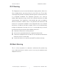
Transition Networks SISGM1040-162D-LR FCC Warning This Equipment has been tested and found to comply with the limits for a Class-A digital device, pursuant to Part 15 of the FCC rules. These limits are designed to provide reasonable protection against harmful interference in a residential installation. This equipment generates, uses, and can radiate radio frequency energy.
Transition Networks SISGM1040-162D-LR Content Introduction................................................................ 1 Benefits .................................................................... 1 Package Contents.................................................... 3 Hardware Description ............................................... 4 Physical Dimension.................................................. 4 Front Panel .............................................................. 4 Top View ......
Transition Networks SISGM1040-162D-LR Commands Level............................................................ 20 Commands Set List......................................................... 21 System Commands Set .................................................. 21 Port Commands Set........................................................ 24 Trunk Commands Set ..................................................... 27 VLAN Commands Set.....................................................
Transition Networks SISGM1040-162D-LR TFTP—Update Firmware....................................... 53 TFTP—Restore Configuration ............................... 54 TFTP—Backup Configuration ................................ 55 System Event Log—Syslog Configuration ............. 56 System Event Log—SMTP Configuration.............. 57 System Event Log—Event Configuration............... 59 Fault Relay Alarm .................................................. 61 SNTP Configuration ...............................
Transition Networks SISGM1040-162D-LR Trap Configuration .......................................................... 88 SNMPV3 Configuration................................................... 89 QoS Configuration ................................................. 92 QoS Policy and Priority Type .......................................... 92 Port Base Priority............................................................ 94 COS Configuration..........................................................
Transition Networks SISGM1040-162D-LR Introduction The 6 10/100/1000T + 2 10/100/1000T/ 100/1000 SFP Combo w/ X-Ring Managed Switch is a cost-effective solution and meets the high reliability requirements demanded by industrial applications. The 6 10/100/1000T + 2 10/100/1000T/ 100/1000 SFP Combo w/ X-Ring Managed Switch can be easily managed through the Web GUI. The fiber port can extend the connection distance to increase network elasticity and performance.
Transition Networks SISGM1040-162D-LR Port Base, Tag Base and Type of Service Priority Port Mirror: Monitor traffic in switched networks TX Packet only RX Packet only Both of TX and RX Packet Security Port Security: MAC address entries/filter IP Security: IP address security management to prevent unauthorized intruder Login Security: IEEE 802.1X/RADIUS IGMP with Query mode for Multi Media Application Case/Installation IP-30 Protection DIN Rail and Wall Mount Design Spanning Tree Support IEEE 802.
Transition Networks SISGM1040-162D-LR Package Contents Please refer to the package content list below to verify them against the checklist. 6 10/100/1000T + 2 10/100/1000T/ 100/1000 SFP Combo w/ X-Ring Managed Switch User manual RS-232/RJ-45 cable Pluggable Terminal Block 2 wall mount plates and 6 screws One DIN-Rail (attached on the switch) Compare the contents of the industrial switch with the standard checklist above. If any item is damaged or missing, please contact the local dealer for service.
Transition Networks SISGM1040-162D-LR Hardware Description This section describes the Industrial switch’s hardware spec, port, cabling information, and wiring installation. Physical Dimension 6 10/100/1000T + 2 10/100/1000T/ 100/1000 SFP Combo w/ X-Ring Managed Switch dimension (W x D x H) is 72mm x 105mm x 152mm Front Panel Shown below is the front panel of the 6 10/100/1000T + 2 10/100/1000T/ 100/1000 SFP Combo w/ X-Ring Managed Switch.
Transition Networks SISGM1040-162D-LR Top View The top panel of the 6 10/100/1000T + 2 10/100/1000T/ 100/1000 SFP Combo w/ XRing Managed Switch has one terminal block connector for two DC power inputs. Top Panel of the industrial switch LED Indicators There are diagnostic LED indicators located on the front panel of the industrial switch. They provide real-time information of system and optional status. The following table provides description of the LED status and their meanings for the switch.
Transition Networks SISGM1040-162D-LR Off Power input 1 is inactive Green Power input 2 is active Off Power input 2 is inactive PWR2 Power input 1 or 2 is inactive or port link Red failure (depends on Fault Relay Alarm configuration) Fault Off Power input 1 and 2 are both active, or no power inputs Green SFP port is linking Blinking Data is transmitting or receiving Off Not connected to network LNK/ACT (for P7, P8 SFP) Green (upper LED) Blinking (upper LED) P1 ~ P8 (RJ-45) Connected to
Transition Networks SISGM1040-162D-LR Wiring the Power Inputs Please follow the steps below to insert the power wire. Insert the positive and negative wires into the V+ and V- contacts on the terminal block connector. Tighten the wire-clamp screws for preventing the wires from loosing.
Transition Networks SISGM1040-162D-LR Wiring the Fault Alarm Contact The fault alarm contacts are in the middle of the terminal block connector as the picture shows below. The switch will provide local indication of a power or port failure, if configured, by opening the relay contacts. The following illustration shows an application example for wiring the fault alarm contacts. Insert the wires into the fault alarm contacts (No.
Transition Networks SISGM1040-162D-LR Mounting Installation DIN-Rail Mounting The DIN-Rail is installed on the industrial switch at the factory. If the DIN-Rail is not installed, please see the following pictures to screw the DIN-Rail onto the switch. Follow the steps below to hang the industrial switch.
Transition Networks SISGM1040-162D-LR 1. First, insert the top of DIN-Rail into the track. 2. Then, lightly push the DIN-Rail into the track. 3. Check if the DIN-Rail is tightened on the track or not. 4. To remove the industrial switch from the track, reverse steps above.
Transition Networks SISGM1040-162D-LR Wall Mount Plate Mounting Follow the steps below to mount the industrial switch with a wall mount plate. 1. Remove the DIN-Rail from the industrial switch; loose the screws to remove the DINRail. 2. Place the wall mount plate on the rear panel of the industrial switch. 3. Use the screws to screw the wall mount plate on the industrial switch. 4. Use the hook holes at the corners of the wall mount plate to hang the industrial switch on the wall. 5.
Transition Networks SISGM1040-162D-LR Hardware Installation This section describes how to physically install the 6 10/100/1000T + 2 10/100/1000T/ 100/1000 SFP Combo w/ X-Ring Managed Switch. Installation Steps 1. Unpack the Industrial switch. 2. Check if the DIN-Rail is screwed on the Industrial switch or not. If not, please refer to DIN-Rail Mounting section for DIN-Rail installation.
Transition Networks SISGM1040-162D-LR Network Application This section provides some sample applications to guide users.
Transition Networks SISGM1040-162D-LR X-Ring Application The industrial switch supports the X-Ring protocol that can help the network recover from a connection failure within 300ms or less, ensuring network reliability. The X-Ring algorithm is similar to Spanning Tree Protocol (STP)/RSTP algorithm but its recovery time is less than STP/RSTP. The following figure illustrates an X-Ring application.
Transition Networks SISGM1040-162D-LR Coupling Ring Application In the network, there may be more than one X-Ring group. The coupling ring function can connect each X-Ring for redundant backup. It can ensure transmissions between two ring groups do not fail. The following figure is a sample coupling ring application.
Transition Networks SISGM1040-162D-LR Dual Homing Application Dual Homing is a function to prevent the connection breaking between an X-Ring group and an upper level/core switch. Assign two ports to be the Dual Homing port that is the backup port in an X-Ring group. The Dual Homing function works only when the X-Ring function is active. Each X-Ring group has only one Dual Homing port.
Transition Networks SISGM1040-162D-LR Console Management Connecting to the Console Port The supplied cable has an RS-232 connector on one end and an RJ-45 connector on the other. Attach the end with the RS-232 connector to a PC or terminal and the other end with the RJ-45 connector to the console port of the switch. The connected terminal or PC must support the terminal emulation program.
Transition Networks SISGM1040-162D-LR Login in the Console Interface When the connection between Switch and PC is ready, turn on the PC and run a terminal emulation program or Hyper Terminal and configure its communication parameters to match the following default characteristics of the console port: Baud Rate: 9600 bps Data Bits: 8 Parity: none Stop Bit: 1 Flow control: None The settings of communication parameters After finishing the parameter settings, click “OK“.
Transition Networks SISGM1040-162D-LR Console login interface CLI Management The system supports a command line interface management–CLI. After you have logged in the system by typing in user name and password, you will see a command prompt. To enter CLI management interface, enter “enable” command.
Transition Networks SISGM1040-162D-LR The following table lists the CLI commands and description. Commands Level Modes Access Method Exit Prompt Method About This Mode1 The user commands available at the user level are a subset of Begin a User EXEC session with Enter logout switch> or quit. your switch. those available at the privileged level. Use this mode to • Perform basic tests. • Displays system information.
Transition Networks SISGM1040-162D-LR EXEC mode. To exit to Enter the global interface configuratio command Interface (with a configuratio specific n interface) n mode, Use this mode to switch enter exit. configure parameters (config-if)# To exist to for the switch and privileged Ethernet ports. while in global EXEC configuration mode, or mode end.
Transition Networks SISGM1040-162D-LR [System Location] system description G [System Description] system contact G [System Contact] show system-info location string xxx Set switch system switch(config)#system description string description xxx Set switch system switch(config)#system contact contact window string xxx E switch>show system-info Show system information ip address G [Ip-address] [Subnet- Configure the IP switch(config)#ip address address of switch 192.168.16.1 255.255.
Transition Networks dhcpserver subnetmask SISGM1040-162D-LR G G [Gateway] dhcpserver dnsip G [DNS IP] dhcpserver leasetime G [Hours] dhcpserver ipbinding switch(config)#dhcpserver mask for DHCP clients subnetmask 255.255.255.0 [Subnet mask] dhcpserver gateway Configure subnet I [IP address] Configure gateway for switch(config)#dhcpserver DHCP clients gateway 192.168.1.254 Configure DNS IP for switch(config)#dhcpserver dnsip DHCP clients 192.168.1.
Transition Networks SISGM1040-162D-LR no security G Disable IP security switch(config)#no security function no security http G Disable IP security of switch(config)#no security http HTTP server no security telnet G Disable IP security of switch(config)#no security telnet telnet server Port Commands Set Command Level Description interface fastEthernet G [Portid] duplex I [full | half] Example Choose the port for switch(config)#interface modification.
Transition Networks no security SISGM1040-162D-LR I Disable security of switch(config)#interface interface fastEthernet 2 switch(config-if)#no security bandwidth type all I Set interface ingress switch(config)#interface limit frame type to fastEthernet 2 ‘accept all frame’ switch(config-if)#bandwidth type all bandwidth type I Set interface ingress switch(config)#interface broadcast-multicast- limit frame type to fastEthernet 2 flooded-unicast ‘accept broadcast, switch(config-if)#ban
Transition Networks SISGM1040-162D-LR or to 256000 kbps for giga ports, and zero means no limit. show bandwidth I Show interfaces switch(config)#interface bandwidth control fastEthernet 2 switch(config-if)#show bandwidth state I [Enable | Disable] Use the state interface switch(config)#interface configuration fastEthernet 2 command to specify switch(config-if)#state Disable the state mode of operation for Ethernet ports. Use the disable form of this command to disable the port.
Transition Networks SISGM1040-162D-LR Trunk Commands Set Command Level Description aggregator priority G [1~65535] aggregator activityport G Example Set port group system switch(config)#aggregator priority priority 22 Set activity port switch(config)#aggregator [Group ID] activityport 2 [Port Numbers] aggregator group G Assign a trunk group switch(config)#aggregator group [GroupID] [Port-list] with LACP active.
Transition Networks SISGM1040-162D-LR show aggregator P Show the information switch#show aggregator 1 of trunk group or switch#show aggregator 2 or switch#show aggregator 3 no aggregator lacp G Disable the LACP switch(config)#no aggreator lacp function of trunk group 1 [GroupID] no aggregator group G Remove a trunk group switch(config)#no aggreator group 2 [GroupID] VLAN Commands Set Command Level Description vlan database P Example Enter VLAN configure switch#vlan database mode Vlanm
Transition Networks SISGM1040-162D-LR IEEE 802.1Q VLAN vlan 8021q name [GroupName] vid [VID] V Change the name of switch(vlan)#vlan 8021q name VLAN group, if the test vid 22 group didn’t exist, this command can’t be applied. vlan 8021q port [PortNumber] access-link untag [UntaggedVID] V Assign a access link switch(vlan)#vlan 8021q port 3 for VLAN by port, if the access-link untag 33 port belong to a trunk group, this command can’t be applied.
Transition Networks SISGM1040-162D-LR [TaggedVID List] switch(vlan)#vlan 8021q trunk 3 hybrid-link untag 5 tag 6-8 show vlan [GroupID] or show vlan no vlan group [GroupID] V switch(vlan)#show vlan 23 Show VLAN information V Delete port base switch(vlan)#no vlan group 2 group ID Spanning Tree Commands Set Command Level Description spanning-tree enable G Example Enable spanning tree switch(config)#spanning-tree enable spanning-tree priority G [0~61440] switch(config)#spanning-tree tree p
Transition Networks SISGM1040-162D-LR spanning-tree hello- G time [seconds] Use the spanning-tree switch(config)#spanning-tree hello-time global hello-time 3 configuration command to specify the interval between hello bridge protocol data units (BPDUs). spanning-tree forward- G time [seconds] Use the spanning-tree switch(config)#spanning-tree forward-time global forward-time 20 configuration command to set the forwarding-time for the specified spanningtree instances.
Transition Networks SISGM1040-162D-LR into the forwarding state. stp-path-priority I [Port Priority] Use the spanning-tree switch(config)#interface port-priority interface fastEthernet 2 configuration switch(config-if)#stp-path-priority command to configure 128 a port priority that is used when two switches tie for position as the root switch. stp-admin-p2p I [Auto|True|False] Admin P2P of STP switch(config)#interface priority on this fastEthernet 2 interface.
Transition Networks SISGM1040-162D-LR qos prioritytype G [port-based|cos- Setting of QOS priority switch(config)#qos prioritytype type only|tos-only|cosfirst|tos-first] qos priority portbased [Port] [lowest|low|middle|high] qos priority cos [Priority][lowest|low|mid dle|high] qos priority tos G G Configure Port-based switch(config)#qos priority Priority portbased 1 low Configure COS switch(config)#qos priority cos 0 Priority middle G Configure TOS Priority switch(config)#qos priority tos 3 h
Transition Networks no igmp-query SISGM1040-162D-LR G Disable IGMP query switch#no igmp-query Mac / Filter Table Commands Set Command Level Description mac-address-table static I Example Configure MAC switch(config)#interface hwaddr address table of fastEthernet 2 [MAC] interface (static).
Transition Networks snmp system-name SISGM1040-162D-LR G [System Name] snmp system-location G [System Location] snmp system-contact G [System Contact] snmp agent-mode G [v1v2c|v3|v1v2cv3] snmp community- Set SNMP agent switch(config)#snmp system- system name name l2switch Set SNMP agent switch(config)#snmp system- system location location lab Set SNMP agent switch(config)#snmp system- system contact contact where Select the agent mode switch(config)#snmp agent-mode v1v2cv3 of SNMP G
Transition Networks SISGM1040-162D-LR security-level [NoAuthNoPriv|AuthNoP riv|AuthPriv] match-rule [Exact|Prifix] views [Read View Name] [Write View Name] [Notify View Name] snmpv3 mibview view G Configure the mibview switch(config)#snmpv3 mibview [View Name] table of SNMPV3 view V1 type Excluded sub-oid type agent 1.3.6.
Transition Networks SISGM1040-162D-LR match-rule [Exact|Prifix] views [Read View Name] [Write View Name] [Notify View Name] no snmpv3 mibview G Remove specified switch(config)#no snmpv3 view mibview table of mibview view V1 type Excluded [View Name] SNMPV3 agent. sub-oid 1.3.6.
Transition Networks SISGM1040-162D-LR switch(config-if)#no monitor 802.1x Commands Set Command Level Description 8021x enable G Example Use the 802.1x global switch(config)# 8021x enable configuration command to enable 802.1x protocols. 8021x system radiusip G [IP address] Use the 802.1x switch(config)# 8021x system system radius IP radiusip 192.168.1.1 global configuration command to change the radius server IP. 8021x system serverport G [port ID] Use the 802.
Transition Networks SISGM1040-162D-LR the NAS ID 8021x misc quietperiod G [sec.] Use the 802.1x misc switch(config)# 8021x misc quiet period global quietperiod 10 configuration command to specify the quiet period value of the switch. 8021x misc txperiod G [sec.] Use the 802.1x misc switch(config)# 8021x misc TX period global txperiod 5 configuration command to set the TX period. 8021x misc supptimeout G [sec.] Use the 802.
Transition Networks SISGM1040-162D-LR I 8021x portstate Use the 802.1x port switch(config)#interface [disable | reject | accept state interface fastethernet 3 | authorize] configuration switch(config-if)#8021x portstate command to set the accept state of the selected port. show 8021x E Displays a summary of switch>show 8021x the 802.1x properties and also the port sates. no 8021x G Disable 802.
Transition Networks SISGM1040-162D-LR SystemLog, SMTP and Event Commands Set Command Level Description systemlog ip G [IP address] systemlog mode G [client|server|both] Example Set System log server switch(config)# systemlog ip IP address. 192.168.1.100 Specified the log switch(config)# systemlog mode mode both show systemlog E Displays system log.
Transition Networks SISGM1040-162D-LR [Systemlog|SMTP|Both] event ring-topology- G change Set X-ring topology switch(config)#event ring- changed event type topology-change both Set port event for switch(config)#interface system log fastethernet 3 [Systemlog|SMTP|Both] event systemlog I [Link-UP|LinkDown|Both] switch(config-if)#event systemlog both event smtp I [Link-UP|Link- Set port event for switch(config)#interface SMTP fastethernet 3 Down|Both] switch(config-if)#event smtp both
Transition Networks SISGM1040-162D-LR sntp enable G Enable SNTP function switch(config)#sntp enable sntp daylight G Enable daylight saving switch(config)#sntp daylight time, if SNTP function is inactive, this command can’t be applied. sntp daylight-period G [Start time] [End time] Set period of daylight switch(config)# sntp daylight- saving time, if SNTP period 20060101-01:01 function is inactive, 20060202-01-01 this command can’t be applied.
Transition Networks SISGM1040-162D-LR time zone list no sntp G Disable SNTP function switch(config)#no sntp no sntp daylight G Disable daylight switch(config)#no sntp daylight saving time X-ring Commands Set Command Level Description Example ring enable G Enable X-ring switch(config)#ring enable ring master G Enable ring master switch(config)#ring master ring couplering G Enable couple ring switch(config)#ring couplering ring dualhoming G Enable dual homing switch(config)#ring du
Transition Networks SISGM1040-162D-LR Web-Based Management This section introduces the configuration and functions of the Web-Based management. About Web-based Management On the CPU board of the switch there is an embedded HTML web site residing in flash memory. This offers advanced management features and allow users to manage the switch from anywhere on the network through a standard browser such as Microsoft Internet Explorer. The Web-Based Management supports Internet Explorer 6.0 or later version.
Transition Networks SISGM1040-162D-LR System Login 1. Launch the Internet Explorer on the PC 2. Key in “http:// “+” the IP address of the switch”, and then Press “Enter”. 3. The login screen will appear right after 4. Key in the user name and password. The default user name and password are the same as “root” 5.
Transition Networks SISGM1040-162D-LR Main Page The home page of the Web-based screen mainly consists of a treeview control item. For more details about each function, please click the ‘+’ symbol of each node to expand the tree structure.
Transition Networks SISGM1040-162D-LR System Information Assign the system name, location and view the system information. System Name: Assign the name of switch. The maximum length is 64 bytes. System Description: Displays the description of switch. This column is read only; cannot be modified. System Location: Assign the switch physical location. The maximum length is 64 bytes. System Contact: Enter the name of contact person or organization. Firmware Version: Displays the switch’s firmware version.
Transition Networks SISGM1040-162D-LR IP Configuration User can configure the IP Settings and DHCP client function DHCP Client: Enable or disable the DHCP client function. When DHCP client function is enabled, the industrial switch will be assigned an IP address from the network DHCP server. The default IP address will be replaced with an IP address which is assigned by the DHCP server. After user click “Apply” button, a pop-up dialog show up.
Transition Networks SISGM1040-162D-LR DHCP Server—System configuration The system provides the DHCP server function. Enable the DHCP server function, the switch system will be a DHCP server. DHCP Server: Enable or Disable the DHCP Server function. Enable – the switch will be the DHCP server on your local network. Low IP Address: the dynamic IP assign range. Low IP address is the beginning of the dynamic IP assigns range. For example: dynamic IP assign range is from 192.168.1.100 ~ 192.168.1.200. 192.168.
Transition Networks SISGM1040-162D-LR DHCP Client—Client Entries When the DHCP server function is active, the system will collect the DHCP client information and display it here.
Transition Networks SISGM1040-162D-LR DHCP Server—Port and IP Bindings You can assign the specific IP address that is the IP in the dynamic IP assign range to the specific port. When the device is connected to the port and asks for dynamic IP assigning, the system will assign the IP address that has been assigned to the connected device.
Transition Networks SISGM1040-162D-LR TFTP—Update Firmware TFTP allows the user to update the switch firmware remotely, via the network. Before updating, make sure you have your TFTP server ready and the firmware image is on the TFTP server. 1. TFTP Server IP Address: Fill in your TFTP server IP. 2. Firmware File Name: the name of firmware image. 3. Click Apply .
Transition Networks SISGM1040-162D-LR TFTP—Restore Configuration You can restore the switch configuration from the TFTP server, but you must put the image file on TFTP server first. The switch will then download the flash image. 1. TFTP Server IP Address: Fill in the TFTP server IP. 2. Restore File Name: Fill in the correct restore file name. 3. Click Apply .
Transition Networks SISGM1040-162D-LR TFTP—Backup Configuration You can save the current switch configuration from the switch to TFTP server, then go to the TFTP restore configuration page to restore the switch configuration. 1. TFTP Server IP Address: Fill in the TFTP server IP. 2. Backup File Name: Fill the file name. 3. Click Apply .
Transition Networks SISGM1040-162D-LR System Event Log—Syslog Configuration Configure the system events that you want to record and the system log server IP. 1. Syslog Client Mode: Select the system log mode – client only, server only, or both S/C. 2. System Log Server IP Address: Assigned the system log server IP. 3. Click Reload to refresh the events log. 4. Click Clear to clear all current events log. 5. After configuring, click Apply .
Transition Networks SISGM1040-162D-LR System Event Log—SMTP Configuration You can set up the mail server IP, mail account, account password, and forwarded email account for receiving the event alert. 1. Email Alert: enable or disable the email alert function. 2. SMTP Server IP: set up the mail server IP address (when Email Alert enabled, this function will then be available). 3. Sender: key in a complete email address, e.g. switch101@123.com, to identify where the event log comes from. 4.
Transition Networks SISGM1040-162D-LR SMTP Configuration interface Technical Support: 1-800-260-1312 International: 00-1-952-941-7600 58
Transition Networks SISGM1040-162D-LR System Event Log—Event Configuration You can select the system log events and SMTP events. When selected events occur, the system will send out the log information. Also, per port log and SMTP events can be selected. After configuring, Click Apply . System event selection: 4 selections – Device cold start, Device warm start, SNMP Authentication Failure, and X-ring topology change. Mark the checkbox to select the event.
Transition Networks SISGM1040-162D-LR Event Configuration interface Technical Support: 1-800-260-1312 International: 00-1-952-941-7600 60
Transition Networks SISGM1040-162D-LR Fault Relay Alarm The Fault Relay Alarm function provides the mechanism for warning when power or port faults are detected. There is a set of relay contacts in the switch, and the contacts are closed when either no fault alarms are configured, or the system is normal. With the check boxes unchecked, the system won’t change the status of the relay when a fault occurs. Please see the segment of ‘Wiring the Fault Alarm Contact’ for reference.
Transition Networks SISGM1040-162D-LR SNTP Configuration You can configure the SNTP (Simple Network Time Protocol) settings. The SNTP allows you to synchronize switch clocks via the Internet. 1. SNTP Client: Enable or disable SNTP function to get the time from the SNTP server. 2. Daylight Saving Time: Enable or disable daylight saving time function. When daylight saving time is enabled, you need to configure the daylight saving time period. 3. UTC Timezone: Set the switch location time zone.
Transition Networks HAW - Hawaiian SISGM1040-162D-LR -10 hours 2 am -11 hours 1 am +1 hour 1 pm +2 hours 2 pm +3 hours 3 pm ZP4 - USSR Zone 3 +4 hours 4 pm ZP5 - USSR Zone 4 +5 hours 5 pm ZP6 - USSR Zone 5 +6 hours 6 pm +7 hours 7 pm +8 hours 8 pm +9 hours 9 pm +10 hours 10 pm +12 hours Midnight Standard Nome, Alaska CET - Central European FWT - French Winter MET - Middle European MEWT - Middle European Winter SWT - Swedish Winter EET - Eastern European, USSR Zone 1 BT - Bagh
Transition Networks SISGM1040-162D-LR Standard NZT - New Zealand 4. SNTP Sever URL: Set the SNTP server IP address. 5. Daylight Saving Period: Set up the Daylight Saving beginning time and Daylight Saving ending time. Both will be different in every year. 6. Daylight Saving Offset (mins): Set up the offset time. 7. Switch Timer: Displays the switch current time. 8. Click Apply .
Transition Networks SISGM1040-162D-LR IP Security The IP security function allows the user to assign 10 specific IP addresses that have permission to access the switch through the web browser for managing the switch. IP Security Mode: When this option is enabled, the Enable HTTP Server and Enable Telnet Server Check boxes will then be available. Enable HTTP Server: When this check box is checked, the IP addresses among Security IP1 ~ IP10 will be allowed to access via HTTP service.
Transition Networks SISGM1040-162D-LR IP Security interface Technical Support: 1-800-260-1312 International: 00-1-952-941-7600 66
Transition Networks SISGM1040-162D-LR User Authentication Here you can change login user name and password for management security. 1. User name: Key in the new user name (The default is “root”) 2. Password: Key in the new password (The default is “root”) 3. Confirm password: Re-type the new password 4.
Transition Networks SISGM1040-162D-LR Port Statistics The following information provides the current port statistic information. Port: The port number. Type: Displays the current speed of connection to the port. Link: The status of linking—‘Up’ or ‘Down’. State: It’s set by Port Control. When the state is disabled, the port will not transmit or receive any packet. Tx Good Packet: The counts of transmitting good packets via this port.
Transition Networks SISGM1040-162D-LR Port Control In Port control, you can view every port status that depended on user setting and the negotiation result. 1. Port: select the port that you want to configure. 2. State: Current port status. The port can be set to disable or enable mode. If the port setting is disable then will not receive or transmit any packet. 3. Negotiation: set auto negotiation status of port. 4. Speed: set the port link speed. 5.
Transition Networks SISGM1040-162D-LR Port Trunk The Link Aggregation Control Protocol (LACP) provides a standardized means for exchanging information between Partner Systems on a link to allow their Link Aggregation Control instances to reach agreement on the identity of the Link Aggregation Group to which the link belongs, move the link to that Link Aggregation Group, and enable its transmission and reception functions in an orderly manner.
Transition Networks SISGM1040-162D-LR the left field. To remove unwanted ports, select the port and click Remove . When LACP enabled, you can configure LACP Active/Passive status for each port on State Activity page. Click Apply . Use Delete to delete Trunk Group. Select the Group ID and click Delete .
Transition Networks SISGM1040-162D-LR Aggregator Information When you have setup the aggregator setting with LACP disabled, you will see the local static trunk group information in here. 1. Group Key: Displays the trunk group ID. 2. Port Member: Displays the members of this static trunk group.
Transition Networks SISGM1040-162D-LR State Activity Having set up the LACP aggregator on the tab of Aggregator Setting, you can configure the state activity for the members of the LACP trunk group. You can tick or cancel the checkbox beside the state display. When you remove the tick mark to the port and click Apply , the port state activity will change to Passive. Active: The port automatically sends LACP protocol packets.
Transition Networks SISGM1040-162D-LR Port Mirroring The Port mirroring is a method for monitoring traffic in switched networks. Traffic through ports can be monitored by one specific port. That means traffic going in or out monitored (source) ports will be duplicated into the mirrored (destination) port. Destination Port: There is only one port that can be selected to be the destination (mirror) port for monitoring both RX and TX traffic which come from source port.
Transition Networks SISGM1040-162D-LR Rate Limiting You can set up every port’s bandwidth rate and frame limitation type. Ingress Limit Frame type: Select the frame type that you expect to filter. The frame types have 4 options for selecting: All, Broadcast/Multicast/Flooded Unicast, Broadcast/Multicast and Broadcast only. Broadcast/Multicast/Flooded Unicast, Broadcast/Multicast and Bbroadcast only types are selectable for ingress frames. But, the egress rate only supports ’All’ frame type.
Transition Networks SISGM1040-162D-LR VLAN configuration A Virtual LAN (VLAN) is a logical network grouping that limits the broadcast domain. This enables isolation of network traffic, so only the members of the VLAN will receive traffic from the same VLAN members. Basically, creating a VLAN from a switch is logically equivalent to reconnecting a group of network devices to another Layer 2 switch. However, all the network devices are still plugged into the same switch physically.
Transition Networks SISGM1040-162D-LR VLAN configuration—Port-based VLAN Packets can go among only members of the same VLAN group. Note all unselected ports are treated as belonging to another single VLAN. If port-based VLAN is enabled, the VLAN-tagging is ignored.
Transition Networks SISGM1040-162D-LR VLAN—Port Based Add interface You will see the VLAN displays. Use Delete Use Edit Note button to delete unwanted VLAN. button to modify existing VLAN group. Remember to execute the ‘Save Configuration’ action, otherwise the new configuration will be lost when switch power is removed.
Transition Networks SISGM1040-162D-LR 802.1Q VLAN Tag-based VLAN is an IEEE 802.1Q specification standard. Therefore, it is possible to create a VLAN across devices from different switch venders. IEEE 802.1Q VLAN uses a technique to insert a “tag” into the Ethernet frames. The Tag contains a VLAN Identifier (VID) that indicates the VLAN numbers. You can create a Tag-based VLAN, and enable or disable GVRP protocol. There are 256 VLAN groups. If 802.
Transition Networks SISGM1040-162D-LR 802.1Q Configuration 1. Enable GVRP Protocol: check the check box to enable GVRP protocol. 2. Select the port that you want to configure. 3. Link Type: There are 3 types of link type. Access Link: Single switch only, allows user to group ports by setting the same VID to those ports. Trunk Link: The extended application of Access Link.
Transition Networks SISGM1040-162D-LR Group Configuration interface 3. You can Change the VLAN group name and VLAN ID. 4. Click Apply .
Transition Networks SISGM1040-162D-LR Rapid Spanning Tree The Rapid Spanning Tree Protocol (RSTP) is an evolution of the Spanning Tree Protocol and provides for faster spanning tree convergence after a topology change. The system also supports STP and the system will auto detect the connected device that is running STP or RSTP protocol. RSTP - System Configuration User can view spanning tree information about the Root Bridge. User can modify RSTP state.
Transition Networks SISGM1040-162D-LR RSTP System Configuration interface Technical Support: 1-800-260-1312 International: 00-1-952-941-7600 83
Transition Networks SISGM1040-162D-LR RSTP - Port Configuration You can configure path cost and priority of every port. 1. Path Cost: The cost of the path to the other bridge from this transmitting bridge at the specified port. Enter a number 1 through 200000000. 2. Priority: Decide which port should be blocked by priority in LAN. Enter a number 0 through 240. The value of priority must be the multiple of 16. 3.
Transition Networks SISGM1040-162D-LR RSTP Port Configuration interface Technical Support: 1-800-260-1312 International: 00-1-952-941-7600 85
Transition Networks SISGM1040-162D-LR SNMP Configuration Simple Network Management Protocol (SNMP) is the protocol developed to manage nodes (servers, workstations, routers, switches and hubs etc.) on an IP network. SNMP enables network administrators to manage network performance, find and solve network problems, and plan for network growth. Network management systems learn of problems by receiving traps or change notices from network devices implementing SNMP.
Transition Networks SISGM1040-162D-LR SNMP System Configuration interface Technical Support: 1-800-260-1312 International: 00-1-952-941-7600 87
Transition Networks SISGM1040-162D-LR Trap Configuration A trap manager is a management station that receives traps, the system alerts generated by the switch. If no trap manager is defined, no traps will issue. Create a trap manager by entering the IP address of the station and a community string. To define management stations as trap manager and enter SNMP community strings and selects the SNMP version. 1. IP Address: Enter the IP address of trap manager. 2. Community: Enter the community string. 3.
Transition Networks SISGM1040-162D-LR SNMPV3 Configuration Configure the SNMP V3 function. Context Table Configure SNMP v3 context table. Assign the context name of context table. Click to add context name. Click Remove to remove unwanted context name. User Profile Configure SNMP v3 user table.. User ID: Set up the user name. Authentication Password: Set up the authentication password. Privacy Password: Set up the private password. Click Click Add to add context name.
Transition Networks SISGM1040-162D-LR SNMP V3 configuration interface Technical Support: 1-800-260-1312 International: 00-1-952-941-7600 90
Transition Networks SISGM1040-162D-LR Group Table Configure SNMP v3 group table. Security Name (User ID): Assign the user name that you have set up in user table. Group Name: Set up the group name. Click Click Add to add context name. Remove to remove unwanted context name. Access Table Configure SNMP v3 access table. Context Prefix: Set up the context name. Group Name: Set up the group. Security Level: Select the access level. Context Match Rule: Select the context match rule.
Transition Networks SISGM1040-162D-LR QoS Configuration You can configure Qos policy and priority setting, per port priority setting, COS and TOS setting. QoS Policy and Priority Type Qos Policy: select the Qos policy rule. Using the 8,4,2,1 weight fair queue scheme: The switch will follow 8:4:2:1 rate to process priority queue from High to lowest queue.
Transition Networks SISGM1040-162D-LR QoS Configuration interface Technical Support: 1-800-260-1312 International: 00-1-952-941-7600 93
Transition Networks SISGM1040-162D-LR Port Base Priority Configure per port priority level. Port: Each port has 4 egress queues – High, Middle, Low, and Lowest. Click Apply . COS Configuration Set up the COS priority level. COS priority: Set up the COS priority level 0~7 with 4 egress queues: High, Middle, Low, Lowest. Click Apply . TOS Configuration Set up the TOS priority. TOS priority: the system provides 0~63 TOS priority level.
Transition Networks SISGM1040-162D-LR IGMP Configuration The Internet Group Management Protocol (IGMP) is an internal protocol of the Internet Protocol (IP) suite. IP manages multicast traffic by using switches, routers, and hosts that support IGMP. Enabling IGMP allows the ports to detect IGMP queries and report packets and manage IP multicast traffic through the switch.
Transition Networks SISGM1040-162D-LR IGMP Configuration interface Technical Support: 1-800-260-1312 International: 00-1-952-941-7600 96
Transition Networks SISGM1040-162D-LR X-Ring X-Ring provides a faster redundant recovery than Spanning Tree topology. The action is similar to STP or RSTP, but the algorithms are different. In the X-Ring topology, every switch should enable X-Ring function and assign two member ports for connecting to the ring. Only one switch in the X-Ring group would be set as the master switch with one of the member ports blocked, called backup port, and another port is called working port.
Transition Networks SISGM1040-162D-LR to be the forwarding port of the Ring Master switch. Enable Coupling Ring: To enable the coupling ring function. Marking the check box to enable the coupling ring function. Coupling port: Assign the member port which is connected to the other ring group. Control port: When Couple Ring check box is marked, you have to assign the control port to form a couple-ring group between the two X-rings.
Transition Networks SISGM1040-162D-LR LLDP Configuration Link Layer Discovery Protocol (LLDP) is defined in the IEEE 802.1AB. It is an emerging standard which provides a solution for the configuration issues caused by expanding LANs. LLDP specifically defines a standard method for Ethernet network devices such as switches, routers and wireless LAN access points to advertise information about themselves to other nodes on the network and store the information they discover. LLDP runs on all 802 media.
Transition Networks SISGM1040-162D-LR Security In this section, you can configure 802.1x and MAC address table. 802.1X/Radius Configuration 802.1x is an IEEE authentication specification that prevents the client from accessing the wireless access point or wired switch until it provides authority, like the user name/password that are verified by an authentication server. System Configuration After enabling the IEEE 802.1X function, you can configure the parameters of this function. 1. IEEE 802.
Transition Networks SISGM1040-162D-LR 802.
Transition Networks SISGM1040-162D-LR 802.1x Port Configuration You can configure 802.1x authentication state for each port. The State provides Disable, Accept, Reject and Authorize. Reject: The specified port is required to be held in the unauthorized state. Accept: The specified port is required to be held in the Authorized state.
Transition Networks SISGM1040-162D-LR Misc Configuration 1. Quiet Period: Set the period during which the port doesn’t try to acquire a supplicant. 2. TX Period: Set the period the port wait for retransmit next EAPOL PDU during an authentication session. 3. Supplicant Timeout: Set the period of time the switch waits for a supplicant response to an EAP request. 4. Server Timeout: Set the period of time the switch waits for a server response to an authentication request. 5.
Transition Networks SISGM1040-162D-LR MAC Address Table Use the MAC address table to ensure port security. Static MAC Address You can add a static MAC address; it remains in the switch's address table, regardless of whether the device is physically connected to the switch. This saves the switch from having to re-learn a device's MAC address when the disconnected or powered-off device is active on the network again. You can add / modify / delete a static MAC address.
Transition Networks SISGM1040-162D-LR Static MAC Addresses interface Technical Support: 1-800-260-1312 International: 00-1-952-941-7600 105
Transition Networks SISGM1040-162D-LR MAC Filtering By filtering MAC addresses, the switch can easily filter the pre-configured MAC address and reduce insecurity. You can add and delete filtering MAC address. MAC Filtering interface MAC Address: Enter the MAC address that you want to filter. Click Add . If you want to delete the MAC address from the filtering table, select the MAC address and click Delete .
Transition Networks SISGM1040-162D-LR All MAC Addresses You can view all of the MAC addresses learned by the selected port. Select the port number. The selected port of static & dynamic MAC address information will be displayed in here. Click Clear MAC Table to clear the dynamic MAC addresses information of the current port shown on the screen.
Transition Networks SISGM1040-162D-LR MAC Address Table—Multicast Filtering Multicasts are similar to broadcasts. They are sent to all end stations on a LAN or VLAN. Multicast filtering determines which end stations can receive the multicast traffic if the connected ports had been included in the specific multicast groups. With multicast filtering, network devices only forward multicast traffic to the ports that are connected to the registered end stations.
Transition Networks SISGM1040-162D-LR Factory Default Reset switch to default configuration. Click Reset to reset all configurations to the default value.
Transition Networks SISGM1040-162D-LR Save Configuration Save all configurations that you have made in the system. Click Save to save the all configuration to the flash memory.
Transition Networks SISGM1040-162D-LR System Reboot Reboot the switch in software reset. Click Reboot to reboot the system.
Transition Networks SISGM1040-162D-LR Troubleshooting Verify the switch is using the right power cord/adapter (DC 12-48V), please don’t use the power adapter with DC voltage higher than 48V, or it may damage the switch. Select the proper UTP cable to construct user network. Please check that is using the right cable.
Transition Networks SISGM1040-162D-LR Technical Specification The 6 10/100/1000T + 2 10/100/1000T/ 100/1000 SFP Combo w/ X-Ring Managed Switch technical specification is following. IEEE 802.3 10Base-T Ethernet IEEE 802.3u 100Base-TX IEEE802.3ab 1000Base-T IEEE802.3z Gigabit fiber IEEE802.3x Flow Control and Back Pressure Standard IEEE802.3ad Port trunk with LACP IEEE802.1d Spanning Tree IEEE802.1w Rapid Spanning Tree IEEE802.1p Class of Service IEEE802.1Q VLAN Tag IEEE 802.
Transition Networks SISGM1040-162D-LR Packet Buffer 1Mbits MAC address 8K MAC address table Flash ROM 4Mbytes DRAM 32Mbytes 10/100/1000TX: 6 ports RJ-45 with Auto MDI/MDI-X function Connector 10/100/1000T/Mini-GBIC Combo: 2 x RJ-45 + 2 x 100/1000 SFP sockets RS-232 interface: RJ-45 type 10/100/1000Base-T: 2-pair UTP/STP Cat. 5e/6 cable EIA/TIA-568 100-ohm (100m) Network Cable SFP (Mini-GBIC): Multi-mode: 50/125µm~62.
Transition Networks Install Operation Temp.
Transition Networks SISGM1040-162D-LR GVRP (256 Groups) Double Tag VLAN (Q in Q)* Private VLAN** Port Trunk with LACP Class of service Quality of service Spanning tree Port mirror LACP Port Trunk: 4 Trunk groups/Maximum 4 trunk members IEEE802.1p class of service Per port provides 4 priority queues. The QoS determined by port, Port based/Tag based, IPv4/IPv6 Different Service IEEE802.1d spanning tree IEEE802.1w rapid spanning tree.
Transition Networks SISGM1040-162D-LR Supports Simple Network Time Protocol to synchronize SNTP system clock in Internet.
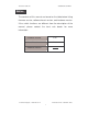
Transition Networks SISGM1040-162D-LR Appendix 10 /100BASE-TX Pin outs With10/100BASE-TX cable, pins 1 and 2 are used for transmitting data, and pins 3 and 6 for receiving data. RJ-45 Pin Assignments Pin Number Assignment 1 Tx+ 2 Tx- 3 Rx+ 6 Rx- [NOTE] “+” and “-” signs represent the polarity of the wires that make up each wire pair. The table below shows the 10 / 100BASE-TX MDI and MDI-X port pin outs.
Transition Networks SISGM1040-162D-LR Straight-through cable schematic Cross over cable schematic 10/100/1000Base-TX Pin outs The following figure shows the 10/100/1000 Ethernet RJ-45 pin outs.
Transition Networks SISGM1040-162D-LR 10/100/1000Base-TX Cable Schematic Straight through cables schematic Cross over cables schematic 120
Transition Networks SISGM1040-162D-LR Gigabit Copper/SFP (mini-GBIC) combo port The Industrial switch has two auto-detect Giga port—UTP/Fiber combo ports. The Gigabit Copper (10/100/1000T) ports should use Category 5e or above UTP/STP cable for connection. The SFP slots are for connecting to the network segment with single or multi-mode fiber. You can choose an appropriate mini-GBIC module to plug into the slots.
Transition Networks SISGM1040-162D-LR First, insert the transceiver into the SFP slot. Notice that the triangle mark is the bottom of the slot. Figure 2.8: Transceiver to the SFP slot Figure 2.
Transition Networks SISGM1040-162D-LR Second, insert the fiber cable of LC connector into the transceiver. Figure 2.
Transition Networks SISGM1040-162D-LR To remove the LC connector from the transceiver, please follow the steps shown below: First, press the upper side of the LC connector to release from the transceiver and pull it out. Figure 2.11: Remove LC connector Second, push down the metal loop and pull the transceiver out by the plastic handle. Figure 2.
Transition Networks SISGM1040-162D-LR Cabling Use four twisted-pair, Category 5e/above cabling for RJ-45 port connection. The cable between the switch and the link partner (switch, hub, workstation, etc.) must be less than 100 meters (328 ft.) long. Fiber segment using single-mode connector type must use 9/125 µm single-mode fiber cable. Fiber segment using multi-mode connector type must use 50 or 62.5/125 µm multimode fiber cable.