
Network Device User's Guide

Installation -- Continued
Grounding the Media Converter
The SAPTF33xx-1xx single-slot chassis comes equipped with grounding lugs
located on the back panel. They require a grounding conductor wire
terminated with a two-hole, compression-type, grounding connector. The
grounding wire -- which must be a copper conductor -- is not included with
the chassis and must be provided by the customer/installer.
The electrical conducting path from the single-slot chassis must:
• Flow via the grounding lugs to the common bonding network (CBN).
• Be of sufficiently low impedance to conduct fault currents likely to be
imposed on the media converter, and
• Enable proper operation of any over-current protection devices.
The conductor must be fastened to the grounding lugs with the enclosed anti-
rotation star-washers and lug-nut fasteners. The applied torque required to the
connector lug-nut fasteners is specified by the connector’s manufacturer.
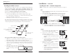
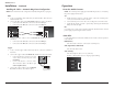
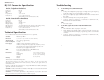
To properly ground the SAPTF33xx-1xx single-slot chassis:
1. Obtain one (1) grounding conductor (12 AWG copper wire gauge or
larger) with a two-hole, compression-type, grounding connector.
2. Attach the grounding conductor to the converter by placing the two-hole
connector onto the grounding lugs and fasten with the enclosed lock-
washers / lug-nuts at the proper torque (per the manufacturer’s
specification).
3. Attach the opposite end of the
grounding conductor to the
common bonding network
(CBN).
g
rounding lugs
earth ground
grounding
connector
and wire
6
SAPTF33xx-1xx
24-hour Technical Support: 1-800-260-1312 -- International: 00-1-952-941-7600
3/4-inch
spacin
g
Grounding lugs
(6-32, 1/8" diam.)
12 AWG copper wir
e
(not included)
Star washer (included)
Lug nuts (included)
Two-hole, compression-type
grounding connector
(not included)
7
techsupport@transition.com Click the “Transition Now” link for a live Web chat.
Installation -- Continued
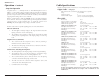
Installing the Cable -- Standard Configuration
NOTE: Unit B MUST be configured for Standard Configuration (see page 4).
Fiber
1. Locate or build fiber cable with male, two-stranded TX to RX connectors
installed at both ends.
2. Connect the fiber cables to Unit A (SAPTF33xx-100) as described:
• Connect the male TX cable connector to the female TX port.
• Connect the male RX cable connector to the female RX port.
3. Connect the fiber cables to Unit B (SAPTF33xx-110) as described:
• Connect the male TX cable connector to the female RX port.
• Connect the male RX cable connector to the female TX port.
Copper
1. Locate or build copper cables with male, RJ-
11C connectors installed at both ends.
2. Connect the copper cables to Unit A
(SAPTF33xx-100) as described:
• Connect the RJ-11C connector at one
end of the cable to the RJ-11C port on
Unit A.
• Connect the RJ-11C connector at the
other end of the cable to the RJ-11C port
on the Central Office.
3. Connect the copper cables to Unit B
(SAPTF33xx-110) as described:
• Connect the RJ-11C connector at one
end of the cable to the RJ-11C port on
Unit B.
• Connect the RJ-11C connector at the
other end of the cable to the RJ-11C port
on the telephone device.
TX RX
ACT
SDF
PWR
TX RX
ACT
SDF
PWR
Connect to the
RJ-11C port on the
Central Office.
Connect to the
RJ-11C port on the
telephone device.
Unit A
Unit B
Unit A
Unit B