
User Guide
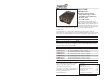

2
S4TEF10xx-11x
24-hour Technical Support: 1-800-260-1312 International: 00-1-952-941-7600
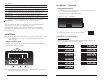
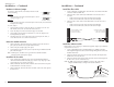
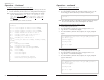
PWR
LKF
100Base-FX
10/100Base-TX
TX
RX
RS-232
4
3
2
1
LNKLNKLNKLNK AISAISAISAIS
fiber port Ethernet port RS-232 port
T1/E1 ports
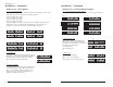
Part Number Fiber-Optic - Single Fiber, Single Mode, 100Base-FX
S4TEF1029-110
SC, 1310 mn TX/1550 nm RX, 20 km (12.4 miles)*
S4TEF1029-111
SC, 1550 mn TX/1310 nm RX, 20 km (12.4 miles)*
Note: S4TEF1029-110 and S4TEF1029-111 are intended to be installed in the same
link where one is the local converter and the other is the remote converter.
S4TEF1029-112
SC, 1310 mn TX/1550 nm RX, 40 km (24.8 miles)*
S4TEF1029-113
SC, 1550 mn TX/1310 nm RX, 40 km (24.8 miles)*
Note: S4TEF1029-112 and S4TEF1029-113 are intended to be installed in the same
link where one is the local converter and the other is the remote converter.
Installation
Note: Because of proprietary communication over fiber, the S4TEF10xx-11x is required
to be installed in pairs, where one is the local converter and the other is the
remote converter.
Copper and fiber ports
The figure below illustrates the locations of the fiber port, the Ethernet port, the RS-
232 port, and the four (4) T1/E1 ports.
*Typical maximum cable distance. Actual distance is dependent upon the physical
characteristics of the network. (TX) = transmit, (RX) = receive
The information in this user’s guide is subject to change. For the most up-to-date
information on the S4TEF10xx-11x media converter, see the user’s guide on-line at:
www.transition.com.
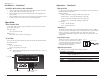
Note: An RS-232 cable with a 6-pin DIN connector and a DB-9 connector is included
with the S4TEF10xx-11x media converter.
S4TEF1035-110 SC, 1550 nm single mode, 120 km (74.6 miles)*
3
techsupport@transition.com -- Click the “Transition Now” link for a live Web chat.
Installation -- Continued
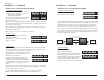
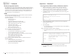
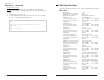
Configuration switches
The S4TEF10xx-11x media converter has two (2) sets of configuration switches.
• Set #1 (upper) sets the T1/E1 options.
• Set #2 (lower) sets the serial/Ethernet options.
Use a flat blade screwdriver to set the switches as shown:
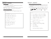
Switch set #1 - T1/E1 options
1, 2, 3, 4 - Line settings
Switches 1, 2, 3, and 4 are used to setup the line settings for the T1/E1 ports. The
selected setting applies to all four (4) T1/E1 channels.
Switch Set #1 (upper): T1/E1 Options
Switch Set #2 (lower): Serial / Ethernet O
p
tions
Key:
up
down
DSX-1, 100 ohm, 266-399 ft. (81-122 m)
DSX-1, 100 ohm, 399-533 ft. (122-162 m)
DSX-1, 100 ohm, 0-133 ft. (0-40.5 m)
DSX-1, 100 ohm, 133-266 ft. (40.5-81 m)
1 2
DS1, 100 ohm, 0 dB LBO
DS1, 100 ohm, -7.5 dB LBO
DSX-1, 100 ohm, 533-655 ft. (162-200 m)
J1, 110 ohm, 0-655 ft. (0-200 m)
3
E1, 120 ohm
DS1, 100 ohm, -15 dB LBO
DS1, 100 ohm, -22.5 dB LBO
41234