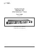
Transition Networks CPSMC08xx-100 8-Slot PointSystem™ Chassis User’s Guide revision B CPSMC0800-100 AC-powered CPSMC0810-100 DC-powered
CPSMC08xx-100 PointSystem™ Chassis Compliance Information CISPR22/EN55022 Class A + EN55024 CE Mark FCC Regulations This equipment has been tested and found to comply with the limits for a Class A digital device, pursuant to part 15 of the FCC rules. These limits are designed to provide reasonable protection against harmful interference when the equipment is operated in a commercial environment.
CPSMC08xx-100 PointSystem™ Chassis Table of Contents 1 2 Introduction . . . . . . . . . . . . . . . . . . . . . . . . . . . . . . . . . . . . . . .4 1.1 Description . . . . . . . . . . . . . . . . . . . . . . . . . . . . . . . . . . . . . . . . . .4 1.2 Unpacking the CPSMC08xx-100 Equipment . . . . . . . . . . . . . . . . .5 Slide-in-Modules . . . . . . . . . . . . . . . . . . . . . . . . . . . . . . . . . . .6 2.1 Media Converter Slide-in-Modules . . . . . . . . . . . . . . . . . . . . . . . . .
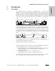
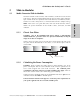
CPSMC08xx-100 PointSystem™ Chassis Introduction 1.1 Description The Transition Networks PointSystem™ CPSMC08xx-100 is a 19-inch, rackmountable chassis for selected Transition Networks media converter slide-inmodules. The chassis allows the network administrator to connect various copper and fiber-optic network media over protocols that include Ethernet, Fast Ethernet, DS3/E3, and OC-12.
CPSMC08xx-100 PointSystem™ Chassis 1.
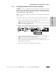
CPSMC08xx-100 PointSystem™ Chassis 2 Slide-in-Modules 2.1 Media Converter Slide-in-Modules Transition Networks media converter slide-in-modules, installed in slots at the front of the chassis, allow the network administrator to connect various copper and fiberoptic network media over protocols that include Ethernet, Fast Ethernet, DS3/E3, and OC-12 as well as many others (see www.transition.com for a complete listing.) 2.1.
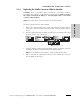
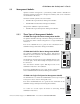
CPSMC08xx-100 PointSystem™ Chassis 2.1.3 Installing the Media Converter Slide-in-Modules CAUTION: Wear a grounding device and observe electrostatic discharge precautions when installing the media converter slide-in-module(s) into the chassis. Failure to observe this caution could result in damage to, and subsequent failure of, the media converter slide-in-module(s). NOTE: The media converter slide-in-modules can be installed in any installation slot, in any order. 1.
CPSMC08xx-100 PointSystem™ Chassis 2.2.4 Replacing the Media Converter Slide-in-Modules CAUTION: Wear a grounding device and observe electrostatic discharge precautions when replacing media converter slide-in-module(s). Failure to observe this caution could result in damage to, and subsequent failure of, the media converter slide-in-module(s). NOTE: The media converter slide-in-modules can be hot-swapped. 1.
CPSMC08xx-100 PointSystem™ Chassis 2.2 Management Modules Optional network management is provided by SNMP software embedded in Transition Networks PointSystem™ management module(s) that can be installed in the CPSMC08xx-100 chassis. Transition Networks provides two such modules: CPSMM-120 Single-Slot Master Management Module. • CPSMM-200 Dual-Slot Master Management Module. slide-in-modules • Along with an additional expansion module: • 2.2.
CPSMC08xx-100 PointSystem™ Chassis 2.2.2 Installing the Management Modules CAUTION: Wear a grounding device and observe electrostatic discharge precautions when installing the management module(s) in the CPSMC08xx-100 chassis. Failure to observe this caution could result in damage to, and subsequent failure of, the management module. To install a management module into the CPSMC08xx-100 chassis: 1a.
CPSMC08xx-100 PointSystem™ Chassis 2.2.3 Replacing the Management Modules CAUTION: Wear a grounding device and observe electrostatic discharge precautions when replacing media converter slide-in-module(s). Failure to observe this caution could result in damage to, and subsequent failure of, the management module(s). To replace a management module in the CPSMC08xx-100 chassis: 1. Remove the management module to be replaced by loosening the panel fastener screw that secures the module to the chassis front.
CPSMC08xx-100 PointSystem™ Chassis 3 Powering the CPSMC08xx-100 The CPSMC08xx-100 chassis can be powered through an AC or DC power supply. An optional auxiliary power supply, with instant fail over protection, is also available. NOTE: The CPSMC08xx-100 chassis does not have an ON/OFF switch. • Power up the chassis by connecting the power supply. • Power-down the chassis by disconnecting power supply. NOTE: Contact Technical Support for any questions concerning power supply. 3.
CPSMC08xx-100 PointSystem™ Chassis 3.1.2 DC Power Supply • This product is intended to be used in a restricted access location. Proper earthing (grounding) is required to ensure safe operation. Grounding terminals are provided (section 4.1.3) for proper grounding of the device as per customer installation requirements and local electrical codes. Prior to installation, use a voltmeter/ohmmeter to check the wiring for the presence of earth ground.
CPSMC08xx-100 PointSystem™ Chassis 3.2 Auxiliary Power Supply The CPSMC08xx-100 chassis can also be supplied with auxiliary power from an external power converter, which is connected to the chassis through the auxiliary power inlet, located on the back panel. (Both and AC and a DC external power converter are available from Transition Networks.
CPSMC08xx-100 PointSystem™ Chassis 3.2.2 DC Auxiliary Power Supply • This product is intended to be used in a restricted access location. Proper earthing (grounding) is required to ensure safe operation. Grounding terminals are provided (section 4.1.3) for proper grounding of the device as per customer installation requirements and local electrical codes. Prior to installation, use a voltmeter/ohmmeter to check the wiring for the presence of earth ground.
CPSMC08xx-100 PointSystem™ Chassis 4 CPSMC08xx-100 Chassis 4.1 Installing the CPSMC08xx-100 Chassis The CPSMC08xx-100 can be installed in a standard 19-inch rack or on a table, shelf, or other stable surface. CAUTION: Install the chassis so that the air flow around it is not restricted. 4.1.1 Table-Top Installation The CPSMC08xx-100 chassis is shipped with nine (9) rubber feet for optional installation on a table or other flat, stable surface in a well-ventilated area.
CPSMC08xx-100 PointSystem™ Chassis To install the CPSMC08xx-100 chassis into a standard 19-inch rack: 1. Determine the preferred alignment of the chassis in the rack. NOTE: Installation bracket mounting screws are provided. Rack mount screws and clip nuts are NOT provided. 2. Locate six (6) installation bracket mounting screws (provided) for each chassis to be installed. WARNING: Mount the chassis evenly and securely onto the rack.
CPSMC08xx-100 PointSystem™ Chassis 4.1.3 Grounding Lugs The CPSMC08xx-100 comes equipped with grounding lugs, which are provided for a grounding conductor wire terminated with a two-hole, compression-type, grounding connector. The grounding wire -- which must be a copper conductor -is not included with the chassis and must be provided by the customer/installer.
CPSMC08xx-100 PointSystem™ Chassis 4.2 Cascade Option The management module cascade option allows the network administrator to connect up to eight (8) CPSMC08xx-100 chassis into one manageable stack, providing a single management source for up to 55 installed media converter devices. DB-9 INPORT 10BASE-T 12C-1 OUTPORT Input Power: 110-240 VAC 1.6A max.
CPSMC08xx-100 PointSystem™ Chassis To cascade two or more CPSMC08xx-100 chassis: 1. Locate one (1) Transition Networks management module cascade cable (with RJ-45 connectors installed at both ends) (P/N 6026) for each set of two (2) chassis to be cascaded. NOTE: Transition Networks management module cascade cables are one (1) meter long. Ensure that the chassis are installed within one (1) meter of each other. 2.
CPSMC08xx-100 PointSystem™ Chassis 4.3 Connecting the Slide-in-Modules to the Network Once the CPSMC08xx-100 chassis has been installed, the media converter slide-inmodules may be connected to the network. CAUTION: Connect input/output network cables ONLY to media converter slidein-module connectors within the same network protocol (such as Ethernet-toEthernet, Fast Ethernet-to-Fast Ethernet, ATM-to-ATM). Failure to observe this caution will cause data transfer to fail. Input Power: 110-240 VAC 1.6A max.
CPSMC08xx-100 PointSystem™ Chassis 5 Network Management The CPSMM100 firmware and the FocalPoint™ application are described in the FocalPoint™ 2.0 Management Application and CPSMM100 Firmware user’s guide (P/N 33293). This manual is included on the application CD and is also available on-line at www.transition.com. Transition Networks CPSMM100 firmware is embedded in the optional management modules (see section 2.2).
CPSMC08xx-100 PointSystem™ Chassis DB-9 Serial Port The DB-9 serial port allows the network administrator to configure and manage the CPSMC08xx-100 chassis using the SNMP Command-Line Interface (CLI) at an attached terminal or terminal emulator. Use a null modem cable to attach a terminal to the DB-9 serial port on the management module as shown. Input Power: 110-240 VAC 1.6A max.
CPSMC08xx-100 PointSystem™ Chassis 6 Troubleshooting 1. Are ANY of the POWER LEDs on any of the slide-in-modules illuminated; AND/OR are the fans operating? YES • The chassis is receiving power. Proceed to the next step. NO • Ensure all power supply cables for proper connection. • Ensure the AC receptacle on the wall is supplying power. • If the fuse for the AC receptacle on the wall blows repeatedly, have the AC receptacle inspected by a qualified electrician.
CPSMC08xx-100 PointSystem™ Chassis Technical Specifications For use with Transition Networks Model CPSMC08xx-100 or equivalent. Dimensions 17 x 10.4 x 1.8 inches (432 x 264 x 46 mm) Shipping Weight 8 lbs. (3.6 kg) AC Power Supply Power Input: Power Output: 100-240 V, 50/60 Hz, 0.66-1.6 Amp (typical with a fully-loaded chassis) +12 VDC at 5 Amp maximum. DC Power Supply Power Input: Power Output: 48-VDC (38 to 58 VDC) @ 1.6 Amp (typical with a fully-loaded chassis) +12 VDC at 8.3 Amp maximum.
CPSMC08xx-100 PointSystem™ Chassis Cable Specifications Null Modem Cable The Null Modem Cable is used for connecting a terminal or terminal emulator to the management module’s DB-9 connector to access the command-line interface. The table below shows the pin assignments for the DB9 cable.
CPSMC08xx-100 PointSystem™ Chassis COAX Cable Coaxial cable media is used for circuits such as DS3, E1 and 10Base-2 Ethernet. The impedance of the coaxial cable is determined by the interface type, for example: • 75 ohm for DS3. • 50 ohm for 10Base-2 Ethernet. Special attention should be given to the grounding requirements of coaxial cable circuits. Installation may require grounding at both cable ends or only one cable end or neither cable end.
CPSMC08xx-100 PointSystem™ Chassis Contact Us Technical Support Technical support is available 24 hours a day. United States: 1-800-260-1312 International: 00-1-952-941-7600 Transition Now Chat live via the Web with a Transition Networks Technical Support Specialist. Log onto www.transition.com and click the Transition Now link. Web-Based Seminars Transition Networks provides 12-16 seminars per month via live web-based training. Log onto www.transition.com and click the Learning Center link.
CPSMC08xx-100 PointSystem™ Chassis Warranty Limited Lifetime Warranty Effective for products shipped May 1, 1999 and after. Every Transition Networks' labeled product purchased after May 1, 1999 will be free from defects in material and workmanship for its lifetime. This warranty covers the original user only and is not transferable.
CPSMC08xx-100 PointSystem™ Chassis Before making any non-warranty repair, Transition Networks requires a $200.00 charge plus actual shipping costs to and from the customer. If the repair is greater than $200.00, an estimate is issued to the customer for authorization of repair. If no authorization is obtained, or the product is deemed not repairable, Transition Networks will retain the $200.00 service charge and return the product to the customer not repaired.