Transition Networks CPSMC0800-100 8-Slot PointSystem™ Chassis User’s Guide (revision A)
CPSMC0800-100 PointSystem™ Chassis Compliance Information UL Listed C-UL Listed (Canada) CISPR22/EN55022 Class A + EN55024 CE Mark FCC Regulations This equipment has been tested and found to comply with the limits for a class A digital device, pursuant to part 15 of the FCC rules. These limits are designed to provide reasonable protection against harmful interference when the equipment is operated in a commercial environment.
CPSMC0800-100 PointSystem™ Chassis Table of Contents 1 2 Introduction . . . . . . . . . . . . . . . . . . . . . . . . . . . . . . . . . . . . . . .4 1.1 Description . . . . . . . . . . . . . . . . . . . . . . . . . . . . . . . . . . . . . . . . . .4 1.2 Unpacking the CPSMC0800-100 Equipment . . . . . . . . . . . . . . . . .5 Slide-in-Modules . . . . . . . . . . . . . . . . . . . . . . . . . . . . . . . . . . .6 2.1 Media Converter Slide-in-Modules . . . . . . . . . . . . . . . . . . . . . . . . .
CPSMC0800-100 PointSystem™ Chassis Introduction 1.1 Description The Transition Networks PointSystem™ CPSMC0800-100 is a 19-inch, rack-mountable chassis for selected Transition Networks Media Converter Slide-In-Modules. The CPSMC0800-100 allows the network administrator to connect various copper and fiber-optic network media over protocols that include Ethernet™, Fast Ethernet™, DS3/E3, and OC-12.
CPSMC0800-100 PointSystem™ Chassis 2.
CPSMC0800-100 PointSystem™ Chassis 2 Slide-in-Modules 2.1 Media Converter Slide-in-Modules Transition Networks Media Converter Slide-in-Modules, installed in slots at the front of the chassis, allow the network administrator to connect various copper and fiberoptic network media over protocols that include Ethernet, Fast Ethernet, DS3/E3, and OC-12 as well as many others (see www.transition.com for a complete listing.) 2.1.
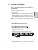
CPSMC0800-100 PointSystem™ Chassis 2.1.2 Installing the Media Converter Slide-in-Modules CAUTION: Wear a grounding device and observe electrostatic discharge precautions when installing the Media Converter Slide-in-Module(s) into the chassis. Failure to observe this caution could result in damage to, and subsequent failure of, the Media Converter Slide-in-Module(s). NOTE: Media Converter Slide-in-Modules can be installed in any installation slot, in any order. 1.
CPSMC0800-100 PointSystem™ Chassis 2.2.3 Replacing the Media Converter Slide-in-Modules CAUTION: Wear a grounding device and observe electrostatic discharge precautions when replacing Media Converter Slide-in-Module(s). Failure to observe this caution could result in damage to, and subsequent failure of, the Media Converter Slide-in-Module(s). NOTE: The Media Converter Slide-in-Modules are hot-swappable. To replace a Media Converter Slide-in-Module: Mpls, MN 55344 CFETF110 Input Power: 110-240 VAC 1.
CPSMC0800-100 PointSystem™ Chassis 2.2 Management Modules Optional network management is provided by SNMP software embedded in Transition Networks PointSystem™ Management Module(s) that can be installed in the CPSMC0800-100 8-Slot chassis. Transition Networks provides two such modules: CPSMM-120 Single-Slot Master Management Module. • CPSMM-200 Dual-Slot Master Management Module. slide-in-modules • Along with an additional expansion module: • 2.2.
CPSMC0800-100 PointSystem™ Chassis 2.2.2 Installing the Managment Modules CAUTION: Wear a grounding device and observe electrostatic discharge precautions when installing the Management Module(s) in the 8-Slot chassis. Failure to observe this caution could result in damage to, and subsequent failure of, the Management Module. Install one (1) Master Management Module (CPSMM-120 or CPSMM-200) in the primary managed CPSMC0800-100 8-Slot chassis.
CPSMC0800-100 PointSystem™ Chassis 2.2.3 Replacing the Mangement Modules CAUTION: Wear a grounding device and observe electrostatic discharge precautions when replacing Media Converter Slide-in-Module(s). Failure to observe this caution could result in damage to, and subsequent failure of, the Management Module(s). NOTE: The Managment Modules are NOT hot-swappable. To replace a Managment Module: 2.
CPSMC0800-100 PointSystem™ Chassis 3 Powering the CPSMC0800-100 The CPSMC0800-100 chassis can be powered through an AC or DC Power Supply. An optional auxilliary power supply, with Instant Fail Over protections, is also available. NOTE: The CPSMC0800-100 8-Slot chassis does not have an ON/OFF switch. • Power up the chassis by connecting the power supply. • Power-down the chassis by disconnecting power supply. WARNING: THE AC AND DC POWER SUPPLIES CONTAIN NO USER-SERVICABLE PARTS.
CPSMC0800-100 PointSystem™ Chassis 3.2 Auxilliary Power Supply The CPSMC0800-100 can also be supplied with auxilliary power through the Auxilliary Power Inlet, located on the back panel. The External Power Converter and additional power cord are sold separately. To power the CPSMM0800-100 8-Slot chassis through the Auxilliary Power Supply: 1. Connect the female end of the External Power Converter to the Auxilliary Power Inlet on the back of the 8-Slot chassis. 2.
CPSMC0800-100 PointSystem™ Chassis 4 CPSMC0800-100 Chassis 4.1 Installing the CPSMC0800-100 Chassis The CPSMC0800-100 can be installed in a standard 19-inch rack or on a table, shelf, or other stable surface. 4.1.1 Standard 19-inch Rack Installation NOTE: The maximum recommended ambient temperature (Tmra) for the 8-Slot chassis is 40°C.
CPSMC0800-100 PointSystem™ Chassis To install the CPSMC0800-100 8-Slot chassis into a standard 19-inch rack: 1. Determine the preferred alignment of the 8-Slot chassis in the rack. NOTE: Installation bracket mounting screws are provided. Rackmount screws and clip nuts are NOT provided. 2. Locate six (6) installation bracket mounting screws (provided) for each chassis to be installed. WARNING: Mount the chassis evenly and securely onto the rack.
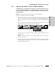
CPSMC0800-100 PointSystem™ Chassis 4.2 Cascade Option The Management Module cascade option allows the network administrator to connect up to eight (8) CPSMC0800-100 8-Slot chassis into one manageable stack, providing a single management source for up to 55 installed Media Converter devices. CFETF110 Mpls, MN 55344 Input Power: 110-240 VAC 1.6A max.
CPSMC0800-100 PointSystem™ Chassis To cascade two or more CPSMC0800-100 8-Slot chassis: 1. Locate one (1) Transition Networks CPSMC0800-100 Management Module cascade cable (with RJ-45 connectors installed at both ends) for each set of two (2) chassis to be cascaded. NOTE: Transition Networks Management Module cascade cables are one (1) meter long. Ensure that the chassis are installed within one (1) meter of each other. 2.
CPSMC0800-100 PointSystem™ Chassis 4.4 Operation Daily operation of the CPSMC0800-100 8-Slot chassis requires no network administrator activity except for the occasional monitoring of the status LED indicators on the installed Media Converter Slide-In-Modules. Each Media Converter Slide-in-Module and each Management Slide-in-Module has one or more LED indicators to help monitor the CPSMC0800-100 PointSystem™ chassis network.
CPSMC0800-100 PointSystem™ Chassis 5 SNMP Agent in the Management Module Both Management Modules (CPSMM-120 and (CPSMM-200) have an SNMP (Simple Network Managment Protocol) Agent installed in the module that allows remote managment of networked devices. The SNMP agent includes the Transition Networks PointSystem™ Command Line Interface (CLI) and an embedded Telnet server.
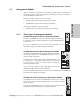
CPSMC0800-100 PointSystem™ Chassis RJ-45 Ethernet™ Port The RJ-45 Ethernet™ Port allows the network administrator to manage the CPSMC1800-100 8-Slot chassis via a remote Network Management Station (NMS) in one of two ways: 1. Using the Transition Networks FocalPoint™ graphical user interface. 2. Using a remote Telnet connection. CFETF110 Network hub or switch connected to the RJ-45 Ethernet port.
CPSMC0800-100 PointSystem™ Chassis 6 Fault Isolation and Correction 1. Are ANY of the POWER LEDs on any of the Slide-in-Modules illuminated; AND/OR are the fans operating? YES • The chassis is receiving power. Proceed to the next step. NO • Ensure all power supply cables for proper connection. • Ensure the AC receptacle on the wall is supplying power. • If the fuse for the AC receptacle on the wall blows repeatedly, have the AC receptacle inspected by a qualified electrician.
CPSMC0800-100 PointSystem™ Chassis Technical Specifications For use with Transition Networks Model CPSMC0800-100 or equivalent. Product is certified by the manufacturer to comply with DHHS Rule 21/CFR, Subchapter J applicable at the date of manufacture. Dimensions 17 x 10.4 x 1.8 inches (432 x 264 x 46 mm) Shipping Weight 8 lbs. (3.
CPSMC0800-100 PointSystem™ Chassis Cable Specifications Null Modem Cable The Null Modem Cable is used for connecting a terminal or terminal emulator to the Management Module’s DB-9 connecdtor to access the command-line interface. The table below shows the pin assignments for the DB9 cable.
CPSMC0800-100 PointSystem™ Chassis Contact Us Technical Support Technical support is avialable 7:00 AM - 6:00 PM CST (GMT -6:00) United States: 1-800-260-1312 International: 00-1-952-941-7600 Transition Now Chat live wia the Web with a Transition Networks Technical Support Specialist. Log onto www.transition.com and click the Transition Now link. Web-Based Seminars Transition Networks provides 12-16 seminars per month via live web-based training. Log onto www.transition.
CPSMC0800-100 PointSystem™ Chassis Warranty Limited Lifetime Warranty Effective for Products Shipped May 1, 1999 and After. Every Transition Networks' labeled product purchased after May 1, 1999 will be free from defects in material and workmanship for its lifetime. This warranty covers the original user only and is not transferable.
CPSMC0800-100 PointSystem™ Chassis ty product(s) back to the customer (any and all customs charges, tariffs, or/and taxes are the customer's responsibility). Before making any non-warranty repair, Transition Networks requires a $200.00 charge plus actual shipping costs to and from the customer. If the repair is greater than $200.00, an estimate is issued to the customer for authorization of repair.