LACT PWR 1000Base-X 10/100/1000 LACT FD LACT PWR FD USB DPX LACTPWR USB LACT 1000Base-X USB 10/100/1000 100Base-FX PWR CBFFG 1000Base-X USB DPX LACTPWR LNK DPX 1000Base-X 1000Base-X 10/100Base-TX 1 PWR LNK USB LNK USB USB 100Base-FX PWR 10/100Base-TX 100Base-X CFBRM 2 LNK USB USB CFBRM FBRM1xxx-1xx & BFFG1xxx-1xx Chassis & Stand-Alone Remotely Managed Devices Manual 33345, Revision D
Transition Networks Table of contents Section I: ..................................................................................................................................................................1 Product Description ................................................................................................................................................1 General description ................................................................................................................
Transition Networks Table of contents, continued Section Vlll: ...........................................................................................................................................................82 Troubleshooting ....................................................................................................................................................82 Troubleshooting problem and corrective action table.......................................................................
Transition Networks Trademark, copyright information, and about this manual Trademark All trademarks and registered trademarks are the property of their respective owners. Copyright restrictions © 2008 Transition Networks: All rights reserved. No part of this work may be reproduced or used in any form or by any means—graphic, electronic, or mechanical—without written permission from Transition Networks. Printed in the U.S.A.
Transition Networks Caution and warnings Definitions Cautions indicate that there is the possibility of poor equipment performance or damage to the equipment. The symbol below identifies cautions Warnings indicate that there is the possibility of injury to person. Cautions and Warnings appear here and may appear throughout this manual where appropriate.
Transition Networks Section I: Product Description In this section These are the topics: Topic General description Product features Management methods Hardware description FBRM/BFFG13xx-1xx fiber-to-fiber gigabit models Redundant SFBRM1040-140 models 24-Hour Technical Support: 1-800-260-1312 International: 00-1-952-941-7600 See Page 2 3 4 5 13 15 1
Section I: FBRM/BFFG Product Description Transition Networks General description Design and configuration The FBRM and BFFG Devices are designed as standalone models, and also as slidein Devices for the Point System chassis. These Devices can be managed through SNMP via the Focal Point software (free), Web-based management, Local SNMP, and USB interfaces.
Transition Networks Section I: FBRM/BFFG Product Description Product features Supported features The following is a list of the major FBRM and BFFG Device supported features: • • • • • • • • • • • • • • • • • • • Remote Management via OAM (IEEE 802.3ah) and IP-based management AutoCross Transparent Link pass-through with automatic link restoration Far end fault detection on fiber ports OAM IEEE 802.
Section I: FBRM/BFFG Product Description Transition Networks Management methods Management The FBRM and BFFG Devices support the following management methods: • • • • USB CLI (Command Line Interface) Telnet MMU (Management Module Unit) chassis web-based IP-based (web-based directly to the Device) USB USB management requires a direct connection to the Device via a computer. This method is used to set up initially or to troubleshoot Devices in the field.
Transition Networks Section I: FBRM/BFFG Product Description Hardware description Front panel CFBRM The front panel of the CFBRM10xx-1xx Devices has the following ports and LEDs: Ports One RJ-45 auto-sensing of 10Base or 10/100Base-TX UTP connections One 100Base-FX/LX/BX fiber either SC or ST connectors One USB Front Panel LEDs • Power (one) • RJ-45 port (two) • LACT (one) • DPX (one) • USB (one) Figure 1: Chassis CFBRM10xx-1xx Device Front Panel Note: The LEDs and ports are the same on the SFBRM10xx-1
Section I: FBRM/BFFG Product Description Transition Networks Hardware description, continued Front panel CFBRM The front panel of the CFBRM 1040-140 Devices has the following ports and LEDs: Ports 100Base-FX SFP port 10/100 Base-T copper port One USB Front Panel LEDs • Power (one) • Link/Active • Speed • Duplex (one) • USB (one) Figure 2: CFBRM1040-100 Front Panel Note: The LEDs and ports are the same on the SFBRM1040-140 standalone models.
Transition Networks Section I: FBRM/BFFG Product Description Hardware description, continued Front panel CFBRM Gbit The front panel of the CFBRM13xx-1xx Devices has the following ports and LEDs: Ports Front Panel LEDs • Power (one) One 100 Base-T • Fiber-Port Link (one) One 1000Base-FX/LX/BX fiber either SC or ST connectors • Fiber-Port Link (one) One USB • USB (one) SC Connector Fiber 100Base-T PWR Power LED SC Connector Fiber USB Port 1000Base-X LNK LNK Fiber Link LED Fiber Link LED USB US
Section I: FBRM/BFFG Product Description Transition Networks Hardware description, continued Front panel CBFFG Gbit The front panel of the CBFFG10xx-1xx Devices has the following ports and LEDs: Ports 1000Base-SX/LX/BX fiber SC port 10/100/1000Base-T copper port One USB Front Panel LEDs • Power (one) • Link/Active • Speed • Duplex (one) • USB (one) Figure 4: CBFFG10xx-1xx Device Front Panel Note: The LEDs and ports are the same on the SBFFG10xx-1xx standalone models.
Transition Networks Section I: FBRM/BFFG Product Description Hardware description, continued Front panel CBFFG Gbit The front panel of the CBFFG1040-1xx Devices has the following ports and LEDs: Ports Front Panel LEDs • Power (one) • Link/Active • Speed • Duplex (one) • USB (one) 1000Base SFP port 10/100/1000Base-T copper port One USB SFP Port Power 1000Base-X Link Active Duplex/Link Speed USB 10/100/1000 RJ45 Port USB Port USB LED Figure 5: CBFFG1040-1xx Device Front Panel Note: The LEDs an
Section I: FBRM/BFFG Product Description Transition Networks Hardware description, continued Front panel CBFFG Gbit The front panel of the CBFFG13xx-1xx Devices has the following ports and LEDs: Ports Front Panel LEDs • Power (one) Two 1000Base-FX/LX/BX fiber either SC or ST connectors • Fiber-Port Link (two) • Duplex (one) One USB • USB (one) Figure 6: Chassis CBFFG13xx-1xx Device Front Panel Note: The LEDs and ports are the same on the SBFFG13xx-1xx standalone models.
Transition Networks Section I: FBRM/BFFG Product Description Hardware description, continued Front panel SFBRM The front panel of the SFBRM1040-140 redundant Devices has the following ports and LEDs: Ports 1000Base SX/LX SFP ports (2 and 3) 10/100/1000Base-T copper port (1) One USB Front Panel LEDs • Power (one) • Link/Active • Duplex • Speed • Duplex (one) • USB (one) Figure 7: CBFFG1040-140 Device Front Panel Continued on next page 24-Hour Technical Support: 1-800-260-1312 International: 00-1-952-9
Section I: FBRM/BFFG Product Description Transition Networks Hardware description, continued Rear panel (standalone) On the standalone SFBRM and SBFFG Devices only, the rear panel consists of a power-barrel connector for connecting power via a power adaptor. See Figure 8. Figure 8: SFBRM/SBFFG 1xxx-1xx Device Real Panel (Standalone Only) Note: The Point System chassis powers the CFBRM and CBFFG chassis Devices.
Transition Networks Section I: FBRM/BFFG Product Description FBRM/BFFG13xx-1xx fiber-to-fiber gigabit models Gigabit (Gbit) models The FBRM100Base-FX-to-1000Base-X and the BFFG 1000Base-X-to-1000Base-X are the Gbit versions of the IEEE 802.3ah managed Devices. The BFFG models link Gbit fiber connections; the FBRM models convert 100Base-Fx 100 Mbit/s to Gbit. These Devices function generally in the same manner as copper-to-fiber FBRMs, the difference is the way the ports are configured.
Section I: FBRM/BFFG Product Description Transition Networks FBRM/BFFG13xx-1xx fiber-to-fiber gigabit models, continued Connectivity The different versions of the FBRM and BFFG can be connected and set up to manage a remote peer completely.
Transition Networks Section I: FBRM/BFFG Product Description Redundant SFBRM1040-140 models Redundant models These SFBRM SFP Devices support fiber redundancy. They have two (2) fiber SFP ports and one (1) copper port. When you tag the fiber ports as primary and secondary with redundancy enabled, any fault on the primary port results in the secondary port becoming operational.
Section I: FBRM/BFFG Product Description Transition Networks Redundant SFBRM1040-140 models, continued 3-port switch mode In this mode, the Device acts as a 3-port switch with the fiber port connected to 2 remote Devices. See Figure 11. Figure 11: 3-Port Switch Mode Note: In 3-port switch mode: • Only one OAM session can be active at anytime. • Transparent Link pass through is not applicable in this scenario. The port link status from the Devices is received only as SNMP traps.
Transition Networks Section II: Hardware Installation Introduction This section describes how to install the CFBRM and CBFFG Devices into a Point System chassis with a remotely managed SFBRM or CFBRM standalone Device. Also, shows how to install two SFBRM Devices or two SBFFG standalone Devices on a network, one as a local Device and the other as a remotely managed Device. Caution When handling chassis Devices observe electrostatic discharge precautions. This requires proper grounding; i.e.
Section ll: FBRM/BFFG Hardware Installation Transition Networks Installing CFBRM/CBFFG Devices into point system chassis IMPORTANT The CFBRM/CBFFG Device product family IS NOT compatible with the CPSMM200 and CPSMM-210 MGMT modules when used in a cascaded application. The CFBRM/CBFFG can be installed in the “master” chassis with the CPSMM-200 MGMT module, but they can not be installed in a cascaded chassis using the CPSMM-210 MGMT module.
Transition Networks Section ll: FBRM/BFFG Hardware Installation Installing SFBRM/SBFFG standalone models Standalone installation Figure 13 shows a typical installation involving two (2) SFBRM/SBFFG standalone Devices on a network. Figure 13: Installation with Two SFBRM/SBFFG Standalone Devices Note: With the local active standalone Device connected to a remote standalone passive Device and with “Mode Control” set to “Auto,” the local (active) Device will manage the remote (passive) Device.
Section ll: FBRM/BFFG Hardware Installation Transition Networks Installing fiber and copper cables Warning Use of controls, any adjustments, or the performance of procedures other than those specified herein may result in hazardous radiation exposure. Visible and invisible laser radiation when open: DO NOT stare into the laserlight beam or view the beam directly with optical instruments. Failure to observe this warning could result in an eye injury or blindness.
Transition Networks Section ll: FBRM/BFFG Hardware Installation Installing fiber and copper cables, continued Caution Copper based media ports, e.g., Twisted Pair (TP) Ethernet, USB, RS232, RS422, RS485, DS1, DS3, Video Coax, etc. are intended to be connected to intra-building (inside building) link segments that are not subject to lightening transients or power faults. Failure to observe this caution could result in damage to equipment.
Section ll: FBRM/BFFG Hardware Installation Transition Networks Connecting power (standalone models) Chassis powers slide-in Device Transition Networks’ Point System chassis powers the CFBRM/CBFFG chassis Devices. Adapter powers standalone Use an AC power adaptor to power the SFBRM/SBFFG standalone Device. To connect power to the Device, do the following: Step 1. Action Connect the barrel connector on the power adapter cord to the power connector on the Device (located on the rear of the Device).
Transition Networks Section ll: FBRM/BFFG Hardware Installation Intentionally Blank 24-Hour Technical Support: 1-800-260-1312 International: 00-1-952-941-7600 23
Transition Networks Section III: USB Driver Installation & COM Port Setup Introduction This section shows how to install the USB driver and configure COM ports.
Transition Networks Section lll: FBRM/BFFG1 Driver Installation & COM Port Setup Installing USB driver USB driver The driver installation instructions are for Windows XP only. Installing the USB driver using Windows 2000 is similar, but not necessarily identical to the following Windows XP driver-installation procedure. Note: The following USB drivers are provided with the product on a CD, also available at www.ftdichip.
Section lll: FBRM/BFFG USB Driver Installation & COM Port Setup Transition Networks Installing USB driver, continued Installing USB driver (continued) Step Action 4. Click the NEXT button to launch the “installation options” dialog box. 5. Select RADIO button “Install from a list or specific location (Advanced)” as shown in Figure 18. Figure 18: Installation Options Dialog Box 6. Click the NEXT button to bring up the “driver search installation options” dialog boxes shown in Figure 19.
Transition Networks Section lll: FBRM/BFFG1 Driver Installation & COM Port Setup Installing USB driver, continued Step 7. Action Use the BROWSE button to locate the USB driver, as shown in Figure 20. C:\FBRM/BFFG1xx Figure 20: Driver Location 8. Click the NEXT button to start installing the driver and the driver-install screen will appear as XP copies the Device driver. See Figure 21.
Section lll: FBRM/BFFG USB Driver Installation & COM Port Setup Transition Networks Installing USB driver, continued Step 9. Action After the driver installation is successful, the “finished installing” dialog box will appear, as shown in Figure 22. Figure 22: Finish Installing Driver Dialog Box 10. Click the FINISH button and a “found new hardware” message will appear on the lower right side of the screen, as shown in Figure 23.
Transition Networks Section lll: FBRM/BFFG1 Driver Installation & COM Port Setup Configuring COM port Getting COM port number You need the COM port number to configure the terminal emulator. To get the COM port number, do the following: Step 1. 2. Action On the desktop, right click on the “my computer” icon and select “Device manager” to open the “computer management” window. Click on “Device manager” to open the Device manager’s panel (screen right panel) shown in Figure 24.
Section lll: FBRM/BFFG USB Driver Installation & COM Port Setup Transition Networks Configuring COM port, continued Terminal emulator setup To set up the terminal emulator software, e.g., HyperTerminal to use the USB COM port, do the following: Step 1. Action Activate the “HyperTerminal” software to bring up the “connection description” dialog box, shown in Figure 25. Figure 25: Connexion Description Diallo Box 2. 3. Type in a name and select an icon.
Transition Networks Section lll: FBRM/BFFG1 Driver Installation & COM Port Setup Configuring COM port, continued Terminal emulator setup (continued) Step Action 4. Select the COM port identified for the USB Device shown in the Device manager. 5. Click the OK button to bring up the “port settings” dialog box, shown in Figure 27. Figure 27: COM Port Settings Dialog Box 6. 7.
Transition Networks Section live: Initial Device Setup Introduction There are four ways to set up the FBRM/BFFG 1xxx-1xx Devices before the Device can be operated and managed: • USB CLI • Telnet • Chassis MMU (chassis model) • IP-based (directly to FBRM/BFFG) The factory default IP configuration is the following: • IP address: 192.168.1.1 • Subnet Mask: 255.255.255.0 • Gateway: 192.168.1.
Transition Networks Section lV: FBRM/BFFG Initial Device Setup USB CLI access Accessing the USB CLI To access the USB CLI, do the following: Step 1. 2. 3. 4. Action Connect the Device to a computer via the USB port. Activate the terminal emulator software to launch the emulator screen. Press the ENTER key to bring up the “password” prompt. Enter the password and then the login (default is “root” in both cases) to bring up the Device console> prompt, shown in Figure 28.
Section IV: FBRM/BFFG Initial Device Setup Transition Networks USB CLI access, continued Redundant The following is the screen of commands for the redundant SFP Devices.
Transition Networks Section lV: FBRM/BFFG Initial Device Setup Initial Device setup via USB CLI IP configuration Use the ‘set’ commands to set the IP configuration through the USB port. Configure the Device with a network IP address, subnet mask, and default gateway. Set the IP address via USB CLI (Command Line Interface), or via DHCP (Dynamic Host Configuration Protocol), which is disabled by default.
Section IV: FBRM/BFFG Initial Device Setup Transition Networks Initial Device setup via USB CLI, continued DHCP method To set the IP configuration via the DHCP in console mode, do the following: Note: Step 1. 2. A DHCP server must be on the network and accessible before using this method. Action At the console> prompt type set dhcp=enable Press the ENTER key and the screen will appear as shown in Figure 31. Figure 31: Enable DHCP 3. 4.
Transition Networks Section lV: FBRM/BFFG Initial Device Setup Initial Device setup via USB CLI, continued Show system configuration To show the Device system configuration, do the following: Step 1. 2. Action At the console> prompt type show Press the ENTER key to bring up the Device system configuration screen, shown in Figure 32.
Section IV: FBRM/BFFG Initial Device Setup Transition Networks Initial Device setup via telnet (directly to Device) To set up the Device initially via telnet directly to the Device, do the following: Initial setup via Telnet to Device Step 1. Action At the command line type: Telnet nnn.nnn.nnn.nnn (IP address of the Device) to bring up the password prompt, shown in Figure 33. Figure 33: Password Prompt 2. 3. Type the case-sensitive username and password (default is ‘root’ for both).
Transition Networks Section lV: FBRM/BFFG Initial Device Setup Initial Device setup via telnet (directly to Device), continued Step 4. 5. Action At the console:/> prompt type show Press the ENTER key to display the system configuration, as shown in Figure 35.
Section IV: FBRM/BFFG Initial Device Setup Transition Networks Initial Device setup via telnet (directly to Device), continued Step 6. 7. Action At the console prompt type: help Press the ENTER key to show the commands, shown in Figure 36. Figure 36: Device Command Screen Note: The CLI and Telnet interface commands are structured in the same manner.
Transition Networks Section lV: FBRM/BFFG Initial Device Setup Initial Device setup via chassis agent MMU, web-based Setup via Web to MMU To set up the Device initially via the MMU web-based, do the following: Step 1. 2. 3. Action Open a web browser. At the URL type the IP address of the chassis (MMU). Click the GO button to bring up the password screen, shown in Figure 37. Figure 37: Chassis Agent (MMU) Log In Screen 4. 5. Type the password (default is private).
Section IV: FBRM/BFFG Initial Device Setup Transition Networks Initial Device setup via chassis agent MMU, web-based, continued Step 7. Action Click the VIEW button of the CFBRM/CBFFG Device in slot 9 to show the local configuration screen for the Device. See Figure 40. Note: You can configure the IP along with other Device parameters on this screen. Figure 40: Local Switch FBRM/BFFG Configuration Screen Note: DO NOT use the browser BACK button to navigate the screens.
Transition Networks Section lV: FBRM/BFFG Initial Device Setup Initial Device setup via chassis agent MMU, web-based, continued IP config via DHCP To configure the IP via DHCP, do the following: Step 1. 2. 3. 4. Action A DHCP server must be on the network and accessible. On the local switch configuration screen, enable DHCP. On the local switch configuration screen set item Reset Switch to “Yes.” Click the SAVE/EXECUTE button to start the DHCP process.
Section IV: FBRM/BFFG Initial Device Setup Transition Networks Initial Device setup IP web-based (directly to Device) Initial setup via IP to Device To set up the Device initially via a IP web-based, do the following: Step 1. 2. 3. Action Open a web browser. At the URL type in the FBRM/BFFG default IP address. Click the GO button to launch the password screen shown in Figure 41. Figure 41: Login Screen 4. 5. Type the password (default is private).
Transition Networks Section lV: FBRM/BFFG Initial Device Setup Initial Device setup IP web-based (directly to Device), continued Step 6. Action Click the local system configuration VIEW button to show the local system configuration menu, shown in Figure 43. Note: You can configure the IP along with other Device parameters on this screen. Figure 43: FBRM/BFFG Local System Configuration Screen Note: DO NOT use the browser BACK button to navigate the screens. This will cause the connection to drop.
Section IV: FBRM/BFFG Initial Device Setup Transition Networks Initial Device setup IP web-based (directly to Device), continued IP config via DHCP To set up the IP configuration via DHCP, do the following: Step 1. 2. Action A DHCP server must be on the network and accessible. On the local switch configuration screen, enable DHCP as shown in Figure 44. Figure 44: IP-based Local System Configuration Screen 3. Click the Local REBOOT button at the top of the screen to start the DHCP process.
Transition Networks Section lV: FBRM/BFFG Initial Device Setup Initial Device setup IP web-based (directly to Device), continued Redundant Devices To set up the redundant feature for the stand-alone 3-port FBRM SFP Device via IP web-based, do the following: Step 1. 2. 3. Action Open a web browser. At the URL type in the SFBRM default IP address. Click the GO button to launch the password screen shown in Figure 45. Figure 45: Login Screen 4. 5. Type the password (default is private).
Section IV: FBRM/BFFG Initial Device Setup Transition Networks Initial Device setup IP web-based (directly to Device), continued Step 6. Action Click the advance system configuration VIEW button to show the redundancy configuration parameters, shown in Figure 47. Figure 47: Redundancy Configuration Screen Note: 48 The redundancy features are specific to the 3-port SFBRM SFP Device only.
Transition Networks Sections V: Device Management In this section These are the topics: Topic SNMP IP-based management Device management via chassis MMU web-based Device management via IP (directly to Device) 24-Hour Technical Support: 1-800-260-1312 International: 00-1-952-941-7600 See Page 50 53 56 49
Section V: FBRM/BFFG Device Management Transition Networks SNMP IP-based management SNMP The FBRM/BFFG Device provides complete management through the SNMP interface.
Transition Networks Section V: FBRM/BFFG Device Management SNMP IP-based management, continued TN private MIBs The TN private MIBs for SNMP IP-based management feature extensive management options.
Section V: FBRM/BFFG Device Management Transition Networks SNMP IP-based management, continued MIB objects Figure 49 shows the placement of the MIB objects on the private tree.
Transition Networks Section V: FBRM/BFFG Device Management Device management via chassis agent (MMU) web-based Management via MMU To set up the FBRM/BFFG initially via the MMU, do the following: Step 1. 2. 3. Action Open a web browser. At the URL type the IP address of the chassis (MMU). Click the GO button to launch the password screen. See Figure 50. Figure 50: Chassis Agent (MMU) Login Screen 4. Type the password (default is private). 5.
Section V: FBRM/BFFG Device Management Transition Networks Device management via chassis agent (MMU) web-based, continued Step 7. Action Click the VIEW button of the CFBRM/CBFFG Device to bring up the local switch management screen. See Figure 53. Figure 53: Local Switch Configuration Screen 8. Scroll down to the LOCAL PORT buttons, shown in Figure 54. Figure 54: Local System Configuration Local Port Buttons Note: DO NOT use the browser BACK button to navigate the screens.
Transition Networks Section V: FBRM/BFFG Device Management Device management via chassis agent (MMU) web-based, continued Step 9. 10. Action Click a PORT BUTTON to bring up the local port switch configuration screen, shown in Figure 55. Scroll down the screen to see the remaining parameters. Note: You can set OAM and other parameters on this screen. Figure 55: Port 1 Local Switch Note: DO NOT use the browser BACK button to navigate the screens. This will cause the connection to drop.
Section V: FBRM/BFFG Device Management Transition Networks Device management via IP web-base (directly to Device) Introduction The FBRM/BFFG Device supports complete Web-based management for viewing statistics and configuring the Device. See the help file on Transition Networks website for more details about different configuration variables. IP web-based management To manage the Device via the IP web-based, do the following: Step 1. 2. 3. 4. Action Open a web browser.
Transition Networks Section V: FBRM/BFFG Device Management Device management via IP web-base (directly to Device), continued IP web-based management (continued) Step Action 5. Click the LOG IN button to bring up the main menu of the Device. See Figure 57. Note: Any Transition Networks FBRM/BFFG remote peer can be completely managed by an FBRM/BFFG local peer through OAM. Figure 57: FBRM/BFFG Main Menu Note: DO NOT use the browser BACK button to navigate the screens.
Section V: FBRM/BFFG Device Management Transition Networks Device management via IP web-base (directly to Device), continued OAM configuration The OAM configuration screen allows enabling or disabling OAM by setting the mode to “active” or “passive.” If the remote Device is a Transition Networks FBRM/BFFG Device, the main menu (PORT button with the remote Device connected) will show the options for managing the remote OAM peer. The Devices are interoperable with other IEEE 802.3ah compliant Devices.
Transition Networks Section VI: Software Features Introduction This section explains the operational status LEDs and what they indicate, along with product features, and the three (3) methods used to upgrade the software.
Section Vl: FBRM/BFFG Software Features Transition Networks Software feature descriptions Note: The FBRM/BFFG Devices does not have configuration switches. Firmware activated features The FBRM/BFFG series Devices features can be configured via USB, MMU, or IP. Table 3 explains the configurable parameters of the Devices.
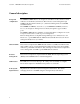
Transition Networks Section Vl: FBRM/BFFG Software Features Software feature descriptions, continued Table 3: Device Software Configurable Features (continued) Feature Description Auto-Negotiation This feature allows the two Devices to configure themselves to achieve the best possible mode of operation over a link, automatically. The Device broadcasts its speed and duplex (full or half) capabilities to the other Device and negotiates the best mode of operation.
Section Vl: FBRM/BFFG Software Features Transition Networks Software feature descriptions, continued Table 3: Device Software Configurable Features (continued) Feature Description Congestion Reduction The FBRM and BFFG Devices do not forward collision signals or error packets between collision domains, which improves baseline network performance. In addition, the Devices filter packets destined for local Devices, which reduces network congestion. Far-End Fault (FEF) FEF is a troubleshooting feature.
Transition Networks Section Vl: FBRM/BFFG Software Features Software feature descriptions, continued Table 3: Device Software Configurable Feature (continued) Feature Description Full Duplex In a full-duplex network, maximum cable lengths are determined by the cable type. See the Cable Specifications section for the different FBRM and BFFG models. The 512-Bit Rule does not apply in a full-duplex network.
Section Vl: FBRM/BFFG Software Features Transition Networks Software feature descriptions, continued Table 3: Device Software Configurable Features (continued) Feature Description Operation Note: On the SFBRM1040-1xx redundant models, there Administration and can be only one (1) OAM session at a time—the Maintenance (OAM, OAM enabled port is user selected. Port 2 fiber is the default port. IEEE 802.3ah-2004 The Device implements the IEEE OAM 802.
Transition Networks Section Vl: FBRM/BFFG Software Features Software feature descriptions, continued Table 3: Device Software Configurable Features (continued) Feature Description Last Gasp/Dying All FBRM/BFFG Devices come equipped with a Last Gasp(OAM, IEEE Gasp/OAM Dying Gasp feature. This feature enables 802.3ah-2004 standard) the Device to store a small amount of power to enable sending an SNMP trap to alert the management console of a power failure.
Section Vl: FBRM/BFFG Software Features Transition Networks Software feature descriptions, continued Table 3: Device Software Configurable Feature (continued) Feature Description OAM Exchange of The remote peer Device (only if a TN configuration FBRM/BFFGDevice) set to passive mode can be information and remote completely managed through the SNMP/Web upgrades with management by its active peer Device when set to organizational specific Active Mode.
Transition Networks Section Vl: FBRM/BFFG Software Features Software feature descriptions, continued Table 3: Device Software configurable Features (continued) Feature Description Pause (flow control) and Pause is used to suspend data transmission temporarily Back Pressure to relieve buffer congestion.
Section Vl: FBRM/BFFG Software Features Transition Networks Software feature descriptions, continued Table 3: Device Software Configurable Features (continued) Description Feature With OAM enabled, TLPT with automatic link Transparent Link-Pass restoration is available for the copper ports on the local Through (TLPT) and and remote peer Devices. When a copper port goes Auto Link Restoration “down,” the information is passed to the other Device and the copper port on that Device will go “down.
Transition Networks Section Vl: FBRM/BFFG Software Features Software security feature descriptions Table 4: Device Software Configurable Security Features Description Security Feature 802.1x MAC filtering When enabled on a port, stops learning all MAC addresses. To allow any frame with a MAC address not in the Static MAC database access, the user needs to add the new address or it will be discarded. This allows filtering any unauthorized access to the network by unknown MAC addresses.
Section Vl: FBRM/BFFG Software Features Transition Networks Software security feature descriptions, continued Table 4: Device Software Configurable Security Features (continued) Description Security Feature When enabled, a link change on Port 2 is passed on to Select Link-Pass Port 1 (twisted pair). For example on a 10/100BaseT-toThrough (LTP) 100Base FX Device, when the (monitored port) fiber goes DOWN, LPT forces the twisted pair DOWN.
Transition Networks Section VIl: Operations Introduction This section explains the operational status LEDs and what they indicate, along with product features, and the three methods use to upgrade the firmware.
Section Vll: FBRM/BFFG Operation Transition Networks Status LEDs Status monitoring LEDS The FBRM series Devices are designed to operate without user intervention. Use the status LEDs to monitor Device operation, once it has been installed in the network. See Figure 59. Figure 59: FBRM Device LEDs LED status tables Tables 5, 6, and 7 explain the status of the power, USB, twisted pair (TP), and fiber LEDs.
Transition Networks Section Vll: FBRM/BFFG Operation Status LEDs, continued Status monitoring LEDS The BFFG copper-to-fiber Gbit series Devices are designed to operate without user intervention. Use the status LEDs to monitor Device operation, once it has been installed in the network. See Figure 60. Figure 60: BFFG Device LEDs LED status tables Tables 8, 9, and 10 explain the status of the power, USB, twisted pair (TP), and fiber LEDs.
Section Vll: FBRM/BFFG Operation Transition Networks Status LEDs, continued Status monitoring LEDs The FBRM Gbit and BFFG Gbit fiber series Devices are designed to operate without user intervention. Use the status LEDs to monitor media-Device operation once installed in the network. See Figure 61.
Transition Networks Section Vll: FBRM/BFFG Operation OAM Device management configuration options OAM mgmt. configuration options OAM Mode control is a feature of the FBRM/BFFG Devices. It can be set to ‘Auto’ (default) or set manually (Active/Passive/Disabled): • In ‘Auto’ Mode, the Device decides the OAM operation • In Manual Mode, the user decides the OAM Mode (Active/Passive/Disabled) Table 13 lists the default configuration.
Section Vll: FBRM/BFFG Operation Transition Networks Firmware upgrades Introduction The firmware image on the Device can be upgraded by these methods: • TFTP protocol • XModem • OAM When enabled, OAM is done automatically when the active peer detects that its remotely managed peer is running a different version of the firmware. TFTP and XModem are initiated by the user. All firmware upgrades are done by the “bootloader.” Note: The bootloader recognizes incompatible FBRM/BFFG BIN files when upgrading.
Transition Networks Section Vll: FBRM/BFFG Operation Firmware upgrades, continued XModem method (continued) Step Action 3. Type “Y” at the prompt. 4. Press the ENTER key to launch the firmware upgrade screen, shown in Figure 63. 10/100BaseT to 100BaseFX IPBased 802.3ah Bridge Version A Copyright (c) 2006 Transition Networks Reading config from flash........done Erasing Application Memory Start sending file through XModem... Transfer completed Checking CRC. . . . . . . .
Section Vll: FBRM/BFFG Operation Transition Networks Firmware upgrades, continued TFTP method The Device can be upgraded remotely using TFTP. A valid IP address, subnet, gateway, TFTP server IP address, and filename must be configured before starting the upgrade process.
Transition Networks Section Vll: FBRM/BFFG Operation Firmware upgrades, continued OAM method OAM firmware upgrades are done by the local active peer Device to its remote passive peer Device automatically. This occurs when the active peer Device finds that its remote peer has a firmware revision different from its own. The active peer Device sends a bootloader command to its remote peer.
Section Vll: FBRM/BFFG Operation Transition Networks Firmware upgrades, continued Accessing the bootloader CLI To access the bootloader CLI to upgrade the firmware, do the following: Step 1. Action When “Transfer Failed” appears on the screen, within ‘2’ seconds, press the CTRL-C keys to bring up the bootloader CLI, as shown in Figure 65. 10/100BaseT to 100BaseFX IP-Based 802.3ah Bridge Version A [Mar 2 2006 09:56:02] Copyright (c) 2006 Transition Networks Reading config from flash........done.
Transition Networks Section Vll: FBRM/BFFG Operation Firmware upgrades, continued Accessing the bootloader CLI (continued) Step Action At the BOOT:> prompt type the letter “t” to establish TFTP as the reboot 3. method. At the BOOT:> prompt type the letter “s” to view system information, as 4. shown in Figure 67. System configuration: IP Address Subnet Mask Default Gateway MAC Address TFTP Server address TFTP Filename BOOT:> : : : : : : 192.251.144.150 255.255.255.0 192.251.144.2 00:c0:f2:00:d1:bc 0.0.
Transition Networks Section Vlll: Troubleshooting Introduction This section provides basic troubleshooting information for the FBRM/BFFG Device via a problem and corrective action table. The problems are stated in the problem column and the action(s) to take for the problem is stated in the corrective action column. If the corrective measures listed do not correct the problem, contact our 24Hour Technical Support department at 1-800-260-1312, International: 00-1-952-9417600.
Section Vlll: FBRM/BFFG Troubleshooting Transition Networks Troubleshooting problem and corrective action table Problem Device does not power up Corrective Action • Is the Device power LED ON? • Is the power adapter’s barrel inserted fully into the Device? • Is the power adapter plugged into an AC outlet? • Is the AC outlet active; if not, check the outlet’s circuit breaker? • Contact Technical Support. US/Canada: 1-800-260-1312, International: 00-1-952-941-7600.
Transition Networks Section Vlll: FBRM/BFFG Troubleshooting Troubleshooting problem and corrective action table, continued Problem Corrective Action The Trap Server does not • Ensure the Trap Server application is running. record traps o In the Windows environment, if the “TN” icon is displayed in the lower right corner of the monitor, then the Trap Server is running. • SNMP traps may be blocked by a router or firewall. Consult your Network administrator to determine if this is the case.
Section Vlll: FBRM/BFFG Troubleshooting Transition Networks Troubleshooting problem and corrective action table, continued Problem Corrective Action The Trap Server does not The response is: record traps,(continued) FLASH: Saving configuration, please wait up to one minute... Writing Flash (04004500,05E8,00FE0000,00FFFFFE) Erasing . Done Erasing/Verifying Writing [000005E8] #[0000FFFF] Done Writing Verifying FLASH: Write complete.
Transition Networks Section Vlll: FBRM/BFFG Troubleshooting Troubleshooting problem and corrective action table, continued Problem Unable to do configuration directly using IP based management on Remote Device Corrective Action • If the OAM session is active, the active local peer Device sends configuration information; if the user attempts to go directly to the remote passive peer Device, the configuration will be overwritten by the OAM update from the local active peer.
Section Vlll: FBRM/BFFG Troubleshooting Transition Networks Intentionally Blank 24-Hour Technical Support: 1-800-260-1312 International: 00-1-952-941-7600 87
Transition Networks Section lX: Copper Cable & Fiber Optic Specifications Introduction This section provides copper and fiber cable specifications.
Section lX: FBRM/BFFG Cable & Fiber Optic Specifications Transition Networks Copper cables Characteristics Cooper cable physical characteristics must meet or exceed IEEE 802.3™ specifications. Copper cable specification Category 5: Gauge: Attenuation: Maximum cable distance: minimum 24 to 22 AWG 22.0 dB/100m @ 100 MHz 100 meter (328 ft.) • • • • Straight-through or crossover twisted-pair cable may be used. See Figure 69. Shielded twisted-pair (STP) or unshielded twisted-pair (UTP) may be used.
Transition Networks Section lX: FBRM/BFFG Cable & Fiber Optic Specifications Fiber optic cable and connector specifications Fiber cable characteristics Cable physical characteristics must meet or exceed IEEE 802.3™ specifications. Parameter Bit Error Rate: Single mode fiber: Multimode fiber: Multimode fiber: Copper-to-fiber connectors Specification <10-9 9 µm 62.5/125 µm 100/140, 85/140, 50/125 µm The following are FBRM10xx-1xx copper-to-fiber connector specifications.
Section lX: FBRM/BFFG Cable & Fiber Optic Specifications Transition Networks Fiber optic cable and connector specifications, continued Copper-to-fiber connectors (continued) Fiber Optics CFBRM1016-100 (extra long haul) SFBRM1016-100 (extra long haul) Fiber-optic transmitter power: Fiber-optic receiver sensitivity: Link budget: CFBRM1017-100 (long wave length) SFBRM1017-100 (long wave length) Fiber-optic transmitter power: Fiber-optic receiver sensitivity: Link budget: CFBRM1035-100 SFBRM1035-100 Fiber-op
Transition Networks Section lX: FBRM/BFFG Cable & Fiber Optic Specifications Fiber optic cable and connector specifications, continued Copper-to-Copper-to-fiber connectors with DMI Fiber Optics CFBRM1011-110 DMI SFBRM1011-110 DMI Fiber-optic transmitter power: Fiber-optic receiver sensitivity: Link budget: CFBRM1013-110 DMI SFBRM1013-110 DMI Fiber-optic transmitter power: Fiber-optic receiver sensitivity: Link budget: CFBRM1014-110 DMI SFBRM1014-110 DMI Fiber-optic transmitter power: Fiber-optic receiver
Section lX: FBRM/BFFG Cable & Fiber Optic Specifications Transition Networks Fiber optic cable and connector specifications, continued Copper-to-fiber connectors with DMI (continued) Fiber Optics CFBRM1029-110 DMI CFBRM1029-111 DMI SFBRM1029-110 DMI SFBRM1029-111 DMI Fiber-optic transmitter power: Fiber-optic receiver sensitivity: Link budget: CFBRM1029-112 DMI CFBRM1029-113 DMI SFBRM1029-112 DMI SFBRM1029-113 DMI Fiber-optic transmitter power: Fiber-optic receiver sensitivity: Link budget: Specificatio
Transition Networks Section lX: FBRM/BFFG Cable & Fiber Optic Specifications Fiber optic cable and connector specifications, continued FBRM fiber-to-fiber Gbit connector Fiber Optics CFBRM1313-100 SFBRM1313-100 Fiber-optic transmitter power: Fiber-optic receiver sensitivity: Link budget: CFBRM1314-100 SFBRM1314-100 Fiber-optic transmitter power: Fiber-optic receiver sensitivity: Link budget: CFBRM1315-100 SFBRM1315-100 Fiber-optic transmitter power: Fiber-optic receiver sensitivity: Link budget: CFBRM131
Section lX: FBRM/BFFG Cable & Fiber Optic Specifications Transition Networks Fiber optic cable and connector specifications, continued FBRM fiber-to-fiber Gbit connectors(continued) Fiber Optics Port 1 Specification CFBRM1335-100 1310 nm multimode SFBRM1335-100 Fiber-optic transmitter power: min: -19.0 dBm max: -14.0 dBm Fiber-optic receiver sensitivity: min: -30.0 dBm max: -14.
Transition Networks Section lX: FBRM/BFFG Cable & Fiber Optic Specifications Fiber optic cable and connector specifications, continued Copper-to-fiber connectors The following are BFFG10x40-100 copper-to-fiber connector specifications.
Section lX: FBRM/BFFG Cable & Fiber Optic Specifications Transition Networks Fiber optic cable and connector specifications, continued BFFG fiber-to-fiber Gbit connectors Fiber Optics Port 1 Specification CBFFG1313-100 1300 nm multimode SBFFG1313-100 Fiber-optic transmitter power: min: -19.0 dBm max: -14.0 dBm Fiber-optic receiver sensitivity: min: -30.0 dBm max: -14.0 dBm 11 dB Link budget: CBFFG1314-100 1300 nm multimode SBFFG1314-100 Fiber-optic transmitter power: min: -19.0 dBm max: -14.
Transition Networks Section lX: FBRM/BFFG Cable & Fiber Optic Specifications Fiber optic cable and connector specifications, continued BFFG fiber-to-fiber Gbit connector (continued) Fiber Optics Port 1 Specification CBFFG1335-100 1300 nm multimode SBFFG1335-100 Fiber-optic transmitter power: min: -19.0 dBm max: -14.0 dBm Fiber-optic receiver sensitivity: min: -30.0 dBm max: -14.
Section lX: FBRM/BFFG Cable & Fiber Optic Specifications Transition Networks Fiber optic cable and connector specifications, continued BFFG fiber-to-fiber Gbit with DMI connector (continued) Fiber Optics Port 1 Specification CBFFG1329-112 DMI CBFFG1329-113 DMI SBFFG1329-112 DMI SBFFG1329-113 DMI 1300 nm multimode Fiber-optic transmitter power: min: -19.0 dBm max: -14.0 dBm Fiber-optic receiver sensitivity: min: -30.0 dBm max: -14.
Transition Networks Section lX: FBRM/BFFG Cable & Fiber Optic Specifications Intentionally Blank 100 24-Hour Technical Support: 1-800-260-1312 International: 00-1-952-941-7600
Transition Networks Section X: Contact Us, Warranty, & Conformity Information Introduction This section explains how to contact Transition Networks via Phone, fax, email, and direct mail.
Transition Networks Section X: FBRM/BFFG Contact Us, Warranty, & Conformity Information Contact us Technical support Technical Support is available 24 hours a day. United States: 1-800-260-1312 International: 00-1-952-941-7600 Live Web chat Chat live via the Web with a Transition Networks Technical Support Specialist. Log onto www.transition.com and click the Transition Now link. Web-based training Transition Networks provides 12-16 seminars per month via live web-based training. Log onto www.
Section X: FBRM/BFFG Contact Us, Warranty, & Conformity Information Transition Networks Conformity declaration Declaration of Conformity Name of Mfg: Transitions Networks 6427 City West Parkway, Minneapolis MN 55344 U.S.A.
Transition Networks Section X: FBRM/BFFG Contact Us, Warranty, & Conformity Information Conformity declaration, continued SBFFG1313-100, SBFFG1314-100, SBFFG1315-100, SBFFG1317-100, SBFFG1335-100, SBFFG1340-100, SBFFG1329-100, SBFFG1329-101, SBFFG1329-102, SBFFG1029-103 SBFFG1313-110, SBFFG1314-110, SBFFG1315-110, SBFFG1317-110, SBFFG1335-110, SBFFG1340-110, SBFFG1329-110, SBFFG1329-111, CBFFG1329-112, SBFFG1029-113 Regulations: Purpose: EMC Directive 89/336/EEC To declare that the CFBRM1xxx-1xx, SFBRM1
Section X: FBRM/BFFG Contact Us, Warranty, & Conformity Information Transition Networks Warranty Limited lifetime warranty Effective for products shipped May 1, 1999 and after. Every Transition Networks’ labeled product purchased after May 1, 1999 will be free from defects in material and workmanship for its lifetime. This warranty covers the original user only and is not transferable.
Transition Networks Section X: FBRM/BFFG Contact Us, Warranty, & Conformity Information Warranty, continued How and where to send the returns Send the defective product postage and insurance prepaid to the following address: CSI Material Management Center c/o Transition Networks 6103 Blue Circle Drive Minnetonka, MN 55343, U.S.A.
Section X: FBRM/BFFG Contact Us, Warranty, & Conformity Information Transition Networks Compliance information Standards CISPR22/EN55022 Class A, CE Mark FCC Regulations This equipment has been tested and found to comply with the limits for a Class A digital Device, pursuant to part 15 of the FCC rules. These limits are designed to provide reasonable protection against harmful interference when the equipment is operated in a commercial environment.
Transition Networks Section X: FBRM/BFFG Contact Us, Warranty, & Conformity Information Compliance information, continued European Regulations, (continued) In accordance with European Union Directive 2002/96/EC of the European Parliament and of the Council of 27 January 2003, Transition Networks will accept post usage returns of this product for proper disposal. The contact information for this activity can be found in the 'Contact Us' portion of this document.
Transition Networks Appendix A: FBRM/BFFG Part Numbers FBRM copper-to-fiber part numbers Standard models The models shown in Table 14 perform as described in this manual. The 110 in the model designation means DMI functionality.
Transition Networks Appendix A: FBRM/BFFG Part Numbers FBRM copper-to-fiber part numbers, continued Single-fiber model pairs The models shown in Table 15 are single-fiber and must be installed in pairs. Table 15: FBRM10xx-1xx Single-Fiber Model Pairs Port 1: Copper Port 2: Fiber Part Number 10/100Base-T 100Base-FX CFBRM1029-100** RJ-45 SC, 100Base-FX BX-U 1310 nm CFBRM1029-110** DMI 100m (328ft) TX/1550nm RX SFBRM1029-100** SM SFBRM1029-110** DMI 20 km (12.
Appendix A: FBRM/BFFG Part Numbers Transition Networks FBRM copper-to-fiber part numbers, continued SFP models The models shown in Table 16 use SFP (small form factor pluggable) Devices sold separately from Transition networks.
Transition Networks Appendix A: FBRM/BFFG Part Numbers FBRM fiber-to-fiber part numbers FBRM Gbit models The models shown in Table 17 are dual-fiber port models. The 11x in the model designation means DMI functionality. Table 17: FBRM13xx-1xx Gbit Models Port 1: Fiber Part Number 100Base-FX CFBRM1313-100 100Base-FX 1300 nm CFBRM1313-110 DMI MM SC 2Km (1.2 miles) SFBRM1313-100 SFBRM1313-110 DMI CFBRM1314-100 100Base-FX 1300 nm CFBRM1314-110 DMI MM SC 2Km (1.
Appendix A: FBRM/BFFG Part Numbers Transition Networks FBRM fiber-to-fiber part numbers, continued Single-fiber models The models shown in Table 18 are single-fiber models and must be installed in pairs. Table 18: FBRM13xx-1xx Single Fiber Model Pairs Port 1: Fiber Part Number 100Base-FX CFBRM1329-100* 100Base-FX 1300 nm CFBRM1329-110* DMI MM SC, 2 Km (1.2 miles) SFBRM1329-100* SFBRM1329-110* DMI 100Base-FX 1300 nm CFBRM1329-101* CFBRM1329-111* DMI MM SC, 2 Km (1.
Transition Networks Appendix A: FBRM/BFFG Part Numbers FBRM fiber-to-fiber part numbers, continued SFP models The models shown in Table 19 use SFP (small form factor pluggable) Devices sold separately from Transition Networks.
Appendix A: FBRM/BFFG Part Numbers Transition Networks BFFG copper-to-fiber part numbers Standard models The models shown in Table 20 perform as described in this manual. Table 20: xBFFGxx-1xx Model Numbers Port 1: Copper Part Number 10/100/1000Base-T CBFFG1040-100 RJ-45 SBFFG1040-100 100m (328ft) Port 2: Fiber 1000Base-X Empty Slot Note: The distances for Port 1 listed in Table 20 are typical maximum distances; the physical characteristics of the network dictate actual distances.
Transition Networks Appendix A: FBRM/BFFG Part Numbers BFFG fiber-to-fiber part numbers Gbit models The models shown in Table 21 perform as described in this manual.
Appendix A: FBRM/BFFG Part Numbers Transition Networks BFFG fiber-to-fiber part numbers, continued Single-fiber models The models shown in Table 22 are single-fiber models and must be installed in pairs.
Transition Networks Appendix A: FBRM/BFFG Part Numbers BFFG fiber-to-fiber part numbers, continued SFP models The models shown in Table 23 use SFP (small form factor pluggable) Devices sold separately from Transition Networks.
Appendix A: FBRM/BFFG Part Numbers Transition Networks Intentionally Blank 24-Hour Technical Support: 1-800-260-1312 International: 00-1-952-941-7600 119
Transition Networks Appendix B: FBRM/BFFG Technical Specification Specifications, notices, and warnings For use with Transition Networks’ Models FBRM and BFFG or equivalent. Parameter IEEE Standards Description IEEE 802.3-2000 IEEE 802.3ah-2004 clause 57, 58 IEEE 802.1q-2003 IEEE 802.1x-2004 IEEE 802.1D IEEE 802.
Appendix B: FBRM/BFFG Technical Specifications Transition Networks Specifications, notices, and warnings, continued Notices • The information in this user’s guide is subject to change. For the most up-to-date information on the FBRM/BFFG Devices, see the user’s guide on-line at: www.transition.com. • Product is certified by the manufacturer to comply with DHHS Rule 21/CFR, Subchapter J applicable at the date of manufacture. • IMPORTANT Copper based media ports: e.g.
Transition Networks Appendix C: Device Commands & Descriptions Command arp clear counter cls exit factory defaults help or ? ifconfig port= Descriptions Displays the arp cache. Clears counters on all ports or on a specific port. Usage: clearcounter [port=] Clears the screen. Exits the CLI/Telnet session. Resets the Device to factory default settings—all current configurations will be erased. Help or ?: Displays the available commands. help : Displays the command usage in detail.
Appendix C: Device Commands & Definitions Command ifoam port= Transition Networks Description OAM configuration for the specified port. Usage: ifoam port= [oam=enable|disable] [oammode=active|passive] [oamrmtloop=enable|disable] OAM: Oammode: netstat ping ps reboot save set set autoupg OAM can be enabled/disabled. OAM Mode can be set to Passive/Active Mode. Oamrmtloop: OAM loopback can be enabled/disable on the remote Device peer. Displays all active and passive sockets.
Transition Networks Command set community set dhcp set downloadcfg set forceupg set gateway set groupstring set uploadcfg set downloadcfg set ip set l3capability set mgmtvlan set niecho set autoupg set forceupg Appendix C: Device Commands & Definitions Description Sets SNMP community name. Usage: set community= Enables/disables DHCP at boot time. In case DHCP failed during initialization, retry using the “restart” option.
Appendix C: Device Commands & Definitions Command set slpt set tlpt set 12cp set fiberredund Set fiberrevert set netmask set orceupg set password set radius set radiusip set radiussecret set snmpaccess set tftpfile set tftpserver set trapmgr set uploadcfg set usb Transition Networks Description Enable/disable Selective Link pass through. Usage: set slpt= Enable/disable Transparent Link pass through.
Transition Networks Command set username show show version Show redundancy show ifcabletest show ifconfig show ifoam show ifrmonstats show ifstats show oamloopback show niecho show 12cp is (L2cp) show oampeer show oamstatistics Appendix C: Device Commands & Definitions Description Sets username for CLI access through serial port/telnet. This username is used when RADIUS is disabled.
Appendix C: Device Commands & Definitions Command snmpget snmpgetn snmpset Transition Networks Description SNMP GET on the OID is performed try "snmpget help" for more information. Usage: snmpget [oid=1.2.3.4 | variable=] • If the ‘oid’ option is used, the indices should be present for table variables and '0' for leaf variables. • If the 'variable' option is used, the leaf variables can be named as is, the table variables have the following format .index1.
Transition Networks Command snmpwalk sys tftpupgrade xmodemupgrade 128 Appendix C: Device Commands & Definitions Description SNMP walk of the entire MIB tree if no options are specified or from OID from the last query if 'continue' is specified. Usage: snmpwalk The system group variables of MIB-II can be configured using the ‘sys’ command. The system contact, name, and location can be set.
Transition Networks Appendix D: IP-Based and Chassis Management Parameters IP- and chassisbased management The chassis Device version of the Devices plugs into a Point System chassis to provide management through the I2C interface: SNMP and web-based management through the MMU. SNMP management is based on the Transition Networks enterprise MIBs. The chassis-based management (via the MMU) provides a subset of the IP-based management via ports.
Transition Networks Appendix D: IP-Based and Chassis Management Parameters Table 26: System Configuration Parameters (continued) Parameter RADIUS Retry RADIUS Secret RADIUS Server Address RADIUS timeout Serial Access Serial Number SNMP Access SNMP Trap Mgr Subnet Mask TFTP Filename TFTP Server Address TFTP upgrade Transparent Link Pass-Through IP based Chassis Description 9 Retries after a network failure. 9 The shared secret between this Device and the RADIUS server.
Appendix D: IP-Based and Chassis Management Parameters Table 25: Media Device Parameters Parameter IP based Chassis 9 Aging Time (Forwarding DB) 9 9 Factory Defaults Flush FDB Flush VLAN DB Histogram Mode 9 9 9 IEEE Priority class 'n' [0-7] 9 IP Traffic class 'n' [1-64] 9 Reset Counters 9 9 Transition Networks Description The aging time (in seconds) for entries in the forwarding database of the switch. This erases all configuration data and sets the Device to factory default settings.
Transition Networks Appendix D: IP-Based and Chassis Management Parameters Table 28: Port Configuration Parameters (continued) Parameter Autocross IP based 9 Chassis 9 Auto-Negotiation 9 9 Connector Type DA Priority Override 9 9 9 Default Forward 9 Default Priority 9 Default VLAN ID 9 Description String 9 Description When enabled, detects and configures the twisted pair port on the Device to the correct MDI or MDI-X configuration automatically.
Appendix D: IP-Based and Chassis Management Parameters Transition Networks Table 28: Port Configuration Parameters (continued) Parameter Discard Tagged IP based 9 Discard Untagged 9 Discard Untagged 9 Double Tagging 9 Duplex Egress Monitor Port 9 9 Chassis 9 Description When enabled, all non-management frames processed as tagged are discarded. If double tagging is enabled, then this check is performed after Ingress double tag removal. Frames with priority and VLAN of “0” are considered tagged.
Transition Networks Appendix D: IP-Based and Chassis Management Parameters Table 28: Port Configuration Parameters (continued) Parameter Egress Rate IP based 9 Far-End Fault Indication Force Def VLAN ID 9 9 Chassis 9 9 Description Controls the effective port transmission rates. The rate limit is provided as a list of pre-defined values: . noLimit(1) . rate64K(2) . rate96K(3) . rate128K(4) . rate160K(5) . rate192K(6) . rate224K(7) . rate256K(8) . rate320K(9) . rate384K(10) . rate512K(11) .
Appendix D: IP-Based and Chassis Management Parameters Transition Networks Table 28: Port Configuration Parameters (continued) Parameter Forward Unknown IP based 9 IEEE Priority class ‘n’ [0-7] 9 IGMP Snoop 9 Ignore Loopback 9 Ignore Wrong Data 9 Ingress Limit mode 9 Ingress Monitor Port 9 IP Traffic 9 Link Partner Autoneg ability Link Partner Pause ability Link Status 9 Chassis 9 9 9 9 9 Description When enabled, unicast frames with unknown destination addresses are allowed to ‘egr
Transition Networks Appendix D: IP-Based and Chassis Management Parameters Table 28: Port Configuration Parameters (continued) Parameter OAM Mode Control IP based 9 Chassis 9 OAM State 9 9 Port Index 9 Port Lock 9 Description This determines how the OAM Modefor ports is configured (manual/auto): • In auto mode, the port defaults to active if in a chassis; passive if a standalone. • In manual mode, the user can choose the OAM mode, using the EFM HUB MIB under the TN private MIB tree.
Appendix D: IP-Based and Chassis Management Parameters Transition Networks Table 28: Port Configuration Parameters (continued) Parameter Pri0 Ingress Rate IP based 9 Chassis 9 Description Rate limit for Priority “0” frames. The rate limit is provided as a list of predefined values: . . . . . . . . . . . . . . . . . . . . . . . . . .
Transition Networks Appendix D: IP-Based and Chassis Management Parameters Table 28: Port Configuration Parameters (continued) Parameter Pri3 Ingress Rate Control IP based 9 Chassis 9 Remote Loopback 9 9 Reset Port Counters SA Priority Override 9 Speed 9 Use Both Traffic class 9 Use IP Traffic class 9 Use Tag Traffic class 9 9 9 9 Description Rate limit for Priority “3” frames to be the same or twice that of the Priority “2” frames. Enable/disable OAM loopback on the remote.
Appendix D: IP-Based and Chassis Management Parameters Transition Networks Table 28: Port Configuration Parameters (continued) Parameter Virtual Cable Test IP based Chassis 9 9 VLAN Status 9 VLAN Table 9 VLAN Tunnel 9 Description The virtual cable test determines the quality of the cable, connectors, and terminations. Problems such as opens, shorts, and cable impendence mismatch can be diagnosed with this test. 802.
Transition Networks Appendix D: IP-Based and Chassis Management Parameters Table 28: Port Configuration Parameters (continued) Parameter VTU Priority Override Static MAC and VLAN tables IP based 9 Chassis Description When enabled, the port checks the frames for VLAN IDs that have the VTU Priority override bit set in the VLAN database.
Transition Networks Appendix E: Request for Comment (RFC) Compliance RFC compliance The following is a list of RFC compliances. [IP] Postel, J. "Internet Protocol DARPA Internet Program Protocol Specification", RFC 791, USC Information Sciences Institute, September 1981. [ICMP] J. Postel “Internet Control Message Protocol. RFC 792, September 1981. [ARP] Plummer, David C., "An Ethernet Address Resolution Protocol", RFC 826. Symbolics Inc., November 1982. [UDP] Postel, J., "Use Datagram Protocol", RFC 768.
Transition Networks Appendix E: Request for Comment (RFC) Compliance RFC compliance (continued) [TFTP] Sollins, K., "The TFTP Protocol (Revision 2)", RFC 1350. MIT, July 1992. [SMTP] Klensin, J. ed., "Simple Mail Transfer Protocol", RFC 2821. AT&T Laboratories, April 2001. [SNMP] Case, J. et al, "A Simple Network Management Protocol (SNMP)", RFC 1157. [1213] Management Information Base for Network Management of TCP/IP-based internets: MIB-II [1493] Definitions of Managed Objects for Bridges.
Transition Networks Index 3-Port Switch..See Redundant SFBRM SFP, 3-Port Switch Auto Link Restore .................................................70 AutoCross description ...........................................................62 Auto-Negotiation description ...........................................................63 Bandwith Allocation description ...........................................................63 Bootloader CLI access ...........................................................
Transition Networks Index USB CLI..............................................................33 web-based via MMU ...........................................43 MAC and VLAN table explanation................................................142 Management IP-based (web).................................................4, 58 MMU ...............................................................4, 55 SNMP ..................................................................52 Telnet.................................