
Home Security System User Manual

6
24-Hour Technical Support: 1-800-260-1312 -- International: 00-1-952-941-7600
Installation
Switches
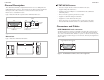
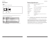
The E-TBT-MC04 has a 3-position DIP switch. See Figure 6. Two of the switches
provide options for enabling and disabling the SQE test and LINK test functions. Both
test functions are Ethernet and 10Base-T standards.
The following describes the switch settings:
SW1 = SQE test: UP is enabled/DOWN is disabled
SW2 = Link test: UP is enabled/DOWN is disabled
SW3 = Duplex: UP is half/DOWN is full
SQE test
The transceiver is shipped from the factory with the SQE test switch enabled. SQE
(Signal Quality Error) is the IEEE term for collisions. Depending on the Ethernet
device attached to the AUI connector, set the SW “1” to the DOWN position to disable
the SQE test function or to the "UP" position to enable the test.
The SQE Test (heartbeat) is a means of detecting a transceiver’s inability to detect
collisions. Without this test, it would not be possible to determine if the collision
detector is operating properly. The SQE test starts by generating a test signal on the
collision pair from the transceiver (or its equivalent) following every transmission on
the network. It does not generate any signals on the common medium.
Additionally, IEEE 802.3 specifications state that IEEE 802.3 compliant repeaters
must not be attached to transceivers that generate the heartbeat.
Link test
For UTP port connection, the E-TBT-MC04 implements the link integrity test
functions as specified in the IEEE 802.3 10Based-T standard. The E-TBT-MC04 will
transmit link test pulses to any UTP port after that port’s transmitter is inactive for a
range of 8 to 17 ms. These pulses are sent to confirm that a valid connection exists
between the E-TBT-MC04 and its attached device.
E-TBT-MC04
SW1
3-Position Switch
SW2
SW3
Front
Figure 6: E-TBT-MC04 Three-Position Switch
techsupport@transition.com -- Click the “Transition Now” link for live Web chat.
7
Installation -- Continued
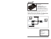
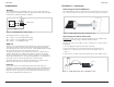
Connecting to a Device AUI port
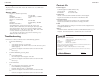
The E-TBT-MC04 can connect to any Ethernet device with an AUI port. To connect to
a device with an AUI port, an AUI cable or direct connection is required. See Figure 7.
Connecting to an RJ-45 device jack
IMPORTANT: If the transceiver is attached to an Ethernet repeater, a10Base-T hub,
or a wiring concentrator, the SQE test function should be disabled.
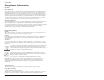
To connect the transceiver to a 10Base-T device via RJ-45 jacks, see Figure 8 and do
the following:
1. Select an appropriate length UTP cable for the connection.
2. Connect one end of the UTP cable to the RJ-45 OUT jack of the transceiver.
3. Route the free end of the UTP cable to the area where the10Base-T device is
located.
4. Connect the free end of the UTP cable to an RJ-45 IN jack on the 10Base-T device.
E-TBT-MC04
E-TBT-MC04
AUI
AUI Cable Length 50 Feet Maximum
AUI Device Interface
E-TBT-MCO4
UTP Cable
RJ-45 Plug
10Based-T
Port
Hub
AUI Cable
Figure 7: E-TBT-MC04 Connected to an AUI Device Port
Figure 8: E-TBT-MC04 Connected to a RJ-45 Device Jack