Multichannel Media Converter 33214.
COMPLIANCE INFORMATION UL Listed C-UL Listed (Canada) CISPR/EN55022 Class A FCC Regulations This equipment has been tested and found to comply with the limits for a class A digital device, pursuant to part 15 of the FCC rules. These limits are designed to provide reasonable protection against harmful interference when the equipment is operated in a commercial environment.
Table of Contents 1. INTRODUCTION . . . . . . . . . . . . . . . . . . . . . . . . . . . . . . . . .1.1 1.1 Multichannel Media Converter Models . . . . . . . . . . . . 1.2 1.2 Media Converter Channels . . . . . . . . . . . . . . . . . . . . . 1.2 1.3 Channel Switches . . . . . . . . . . . . . . . . . . . . . . . . . . . . 1.3 1.4 Reset Button . . . . . . . . . . . . . . . . . . . . . . . . . . . . . . . . 1.3 1.5 AC Power Supply Module/Optional Redundant AC Power Supply Module . . . . . . . . . . .
3. OPERATION . . . . . . . . . . . . . . . . . . . . . . . . . . . . . . . . . . . . .3.1 3.1 Using Status LEDs . . . . . . . . . . . . . . . . . . . . . . . . . . . . 3.2 3.2 Using a Terminal Emulator . . . . . . . . . . . . . . . . . . . . . 3.3 3.3 Using Multiport Management Software at Remote NMS 3.6 4 MAINTENANCE . . . . . . . . . . . . . . . . . . . . . . . . . . . . . . . . . .4.1 4.1 Fault Isolation and Recovery . . . . . . . . . . . . . . . . . . . . 4.2 4.
1. INTRODUCTION The TRANSITION Networks METTF10xx (Ethernet™) and MFETF10xx (Fast Ethernet™) series Multichannel Media Converters connect twisted-pair copper cable to fiber-optic cable in separate copper-to-fiber media converter pairs, called channels. The network administrator can select a Multichannel Media Converter that provides up to six (6) or up to twelve (12) channels, with either 10BASE-T/10BASE-FL or 100BASE-TX /100BASE-FX connections and with either ST or SC fiber connectors.
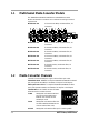
1.1 Multichannel Media Converter Models The TRANSITION Networks METTF10xx and MFETF10xx series Multichannel Media Converters can be selected according to network requirements: MFETF1011-120 Tx Tx Rx 12-channel 100 Mb/s, multimode fiber, ST connectors Tx Rx Rx Tx Tx Rx Rx Tx Rx FDX T-LNK F-LNK 3 2 1 ACTIVE Tx Tx Rx Tx Rx Rx Tx 1.
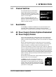
1 INTRODUCTION 1.3 Channel Switches Full-duplex/half-duplex mode selection switches (DIP switches #1-6) allow the network administrator to set EACH media converter channel, separately, either to fullduplex or to half-duplex. The Link Test switch (DIP switch #7) enables or disables the Missing Link Test feature for a block of six (6) Multichannel Media Converter channels. 1.
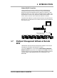
1.6 Multichannel Media Converter Management Module TRANSITION Networks Multichannel Media Converters are shipped with a Management Module installed and functional. Embedded SNMP software in the Management Module allows network management of the Multichannel Media Converter. Connections to Management Module The network administrator can manage the Multichannel Media Converter using Management Module SNMP software accessed either through the PS/2 serial port or through the RJ-45 network port.
1 INTRODUCTION Network RJ-45 Connection The RJ-45 Ethernet connection permits the network administrator to manage the Multichannel Media Converter using the TRANSITION Networks Multiport Management Software graphical interface (or other SNMP application) at a remote network management station (NMS). The RJ-45 Ethernet connection also permits the network administrator to use a remote Telnet connection to the Multichannel Media Converters.
2 INSTALLATION Direction for installing the TRANSITION Networks Multichannel Media Converter is provided in the pages that follow. 2.1 2.2 2.3 Preparing the Site ..................................................................2.2 Unpacking METTF10xx, MFETF10xx Equipment ....................2.3 Installing Optional Redundant Power Supply Module ...........2.4 2.3.1 2.3.2 2.4 Installing Multichannel Media Converter at Site ....................2.6 2.4.1 2.4.2 2.5 2.6 2.9 Standard Rack Installation ....
2.1 Preparing the Site Consider the following when choosing a site for the Multichannel Media Converter: • Select a site that provides conditions that conform to the environmental requirements listed in the appendix. • Select a site that is dust-free and moisture-free. • Do not block the ventilation openings on the Multichannel Media Converter. The site should allow for proper heat dissipation from, and adequate ventilation around, the Multichannel Media Converter.
2 INSTALLATION 2.2 Unpacking METTF10xx, MFETF10xx Equipment Use the following list to verify the shipment: Item Multichannel Media Converter Rack mounting kit Four self-adhesive rubber feet Power Cord Management Control Cable Muliipoint Management Software Disk Redundant Power Supply Module (with Power Cord) User’s Guide MULTICHANNEL MEDIA CONVERTER 2.
2.3 Installing Optional Redundant Power Supply Module The standard Multichannel Media Converter is shipped with one MAIN Power Supply Module installed at the back of the Multichannel Media Converter cabinet and with a protective plate covering an installation slot intended for a second, optional BACKUP Power Supply Module.
2 INSTALLATION 6. Carefully slide the Management Module back into the Multichannel Media Converter. Ensure that the frame of the Management Module runs smoothly between the guides at the bottom of the Multichannel Media Converter. Note a slight resistance just before the Management Module frame comes flush with the rear panel of the Multichannel Media Converter. At this point, ensure that the edges of the Management Module run parallel to the corresponding edges of the Multichannel Media Converter.
2.4 Installing Multichannel Media Converter at Site The Multichannel Media Converter can be installed in a standard rack or on a table, shelf, or other stable surface. 2.4.1 Standard Rack Installation NOTE: Installation bracket mounting screws are provided. Rackmount screws and clip nuts are NOT provided.
2 INSTALLATION 2.4.2 Table-Top Installation The Multichannel Media Converter is shipped with four (4) rubber feet for optional installation on table or other flat, stable surface. CAUTION: Do not place the Multichannel Media Converter on active, heat generating equipment and avoid placing other devices on top of the Multichannel Media Converter. Failure to observe this caution could cause Multichannel Media Converter to fail. 1. Select a level, secure surface in a well-ventilated area. 2.
2.5 Powering the Multichannel Media Converter NOTE: The Multichannel Media Converter does NOT have a power ON/OFF switch. Power is applied to, and removed from, the Multichannel Media Converter by connecting and disconnecting the power cord. NOTE: The Main Power Supply Module and the Redundant (backup) Power Supply Module each has a separate power cord.
2 INSTALLATION 2.6 Connecting Channel Ports to Network Each channel port is connected, using twisted-pair copper and fiber-optic cable, to network devices. 2.6.1 Setting FDX/HDX Channel Configuration Switches FDX/HDX (F(ull-)D(uple)X and H(alf)D(uple)X) refers to the manner in which a network device sends and receives data on the network. A network device that is operating in half-duplex mode either sends data or receives data, in turn.
2.6.2 Installing Fiber-optic Cable Refer to the appendix for cable specifications for the 10BASE-FL or the 100BASE-FX fiber-optic installation. Installing Cable 1. Locate or build 10BASE-FL-compliant or 100BASE-FX-compliant cables (depending upon Multichannel Media Converter selected for the site), with male two-stranded TX to RX connectors installed at both ends. 2. Connect TX and RX connectors at one end of cable to mating Multichannel Media Converter TX and RX fiber-optic connector. 3.
2 INSTALLATION To perform a link test: 1. Verify that all network devices connected to the fiber-optic ports on the Multichannel Media Converter are powered ON and operational. 2. Cycle power to the Multichannel Media Converter by ptessing the RESET botton, if preseny, or bydisconnecting the power cord from the external AC outlet and then reconnecting the power cord to the external AC outlet. Verify that the Multichannel Media Converter is powered ON and is operational: • 3.
2.7 Setting Network Management Parameters CAUTION: IP parameters should be set and/or modified ONLY at the attached terminal Interface. To set the Multichannel Media Converter network parameters: 1. Locate a PC equipped with any terminal emulation program. 2. Connect the Multichannel Media Converter to the PC by connecting the miniDIN end of the control cable (provided) to the Multichannel Media Converter Management PS/2 port and the other end of the cable to the PC DB-9 serial port connector.
2 INSTALLATION (M)odify any of this or (C)ontinue? [M] m For each of the following questions, you can press to select the value shown in braces, or you can enter a new value. NETWORK PARAMETERS: ------------------Do you want a LAN interface? [Y] This board's LAN IP address(0.0.0.0 = RARP)? [192.168.1.99] Use a subnet mask for the LAN interface? [N] y Subnet mask for LAN (0 for none)? [0.0.0.0] Should there be a default gateway for packet routing? [N] y What is its IP address? [0.0.0.
2.8 Connecting to TCP/IP Network Management at Remote Network Management Station (NMS) It is recommended that the Multichannel Media Converter RJ-45 MANAGEMENT port be connected to the TCP/IP network management station (NMS) through a switch or a hub that also is connected to other managed network devices. If the Multichannel Media Converter RJ-45 MANAGEMENT port is connected directly to the NMS, the NMS will manage only that Multichannel Media Converter. 1.
2 INSTALLATION 2.9 Installing Multiport Management Software at Remote NMS NOTE: Multiport Management Software 1.0 runs on a variety of platforms. On most Win32* platforms, Multiport Management Software 1.0 can be used as "standalone" or as an integrated component with HP Open View. Using HP Open View on HP UX Unix and Solaris, Multiport Management Software runs only as an integrated component ; there is no "standalone" Unix version of this software.
3. OPERATION Daily operation of the TRANSITION Networks METTF10xx, MFETF10xx Multichannel Media Converter requires no network administrator activity except the occasional monitoring of status LED indicators at the front of the Multichannel Media Converter. Optionally, the network administrator can monitor and manage the Multichannel Media Converter using an attached terminal or terminal emulator or at a remote Telnet connection.
3.1 Using Status LEDs Status LEDs monitor Multichannel Media Converter operation. Power Supply and Link Test Switch LEDs LED Color MAIN Amber is functional. Indicates The main power supply 0BASE-TX to 100BASE-FX Weak/flashing Amber The main power supply is failing or failed. Green The optional redundant power supply, if installed, is functioning normally. Weak/flashing Green The optional redundant power supply, if installed, is failing or failed.
3 OPERATION 3.2 Using a Terminal Emulator The Multichannel Media Converter Management Module terminal emulator interface permits the network administrator to display status messages and to display and to modify selected network settings. CAUTION: IP parameters can be set and/or modified ONLY at the attached terminal Interface. The Multichannel Media Converter command-line interface is accessible using a terminal or terminal emulator attached to the PS/2 serial port on the Multichannel Media Converter.
Using Terminal Emulator Thrn the main menu comes up with the following options: 1. Device status 2. Device control 3. File download (TFTP) Select (1-3): NOTE: The TFTP feature is NOT enabled in the current software version.
3 OPERATION At the main menu, select option 2 to display the device control menu, which allows the network administrator to reset the Multichannel Media Converter cards, to change test mode, and to enter the duplex mode change menu. Device control: =============== 1. Reset bottom card. 2. Change bottom test. 3. Reset top card. 4. Change top test. 5. Change HDX commands. 0. Main menu. Select (0-5): NOTE: Options 3 and 4 do not appear in Multichannel Media Converters with only six channels.
3.3 Using Multiport Management Software at Remote NMS The LED indicators available on the physical METTF10xx or MFETF10xx Multichannel Media Converter also can be displayed graphically at a remote network management station (NMS), using installed TRANSITION Networks Multiport Management Software. The Multiport Management Software brings up a drawing that represents each selected managed METTF10xx or MFETF10xx Multichannel Media Converter, identified by IP address.
3 OPERATION NOTE: Click the Help button OR the ? button on any screen to bring up links to an integrated set of HELP screens that CAN BE VIEWED AND PRINTED FROM ANY STANDARD HTML BROWSER: The followng conventions are used at the Multiport Management Software graphical interface: TP* Link, Fiber Link, TP* Activity, and Fiber Activity are either green for up/detected or dim gray for down/not detected.
4 MAINTENANCE 4 MAINTENANCE Maintenance direction for the TRANSITION Networks Multichannel Media Converter provided in this section includes: 4.1 4.2 Fault Isolation and Recovery .................................................4.2 Hardware Replacement Procedures ......................................4.5 4.2.1 4.2.2 Replacing Management Module ..............................4.5 Replacing AC Power Supply Module ......................4.6 MULTICHANNEL MEDIA CONVERTER 4.
4.1 Fault Isolation and Recovery Determine the answers to the following questions and, where appropriate, take the indicated action(s): 1. Does Multichannel Media Converter Reset Correct the Condition? • Press the RESET button at the front of the Multichannel Media Converter Management Module for about one (1) second. The LEDs at the front of the Multichannel Media Converter should flash once, then the Multichannel Media Converter should return to normal network operation. • 2. Observe the results.
4 MAINTENANCE 3. Are Channel Links Good? If the T-LNK LED for a twisted pair port is OFF: • Ensure the network device connected to the twisted-pair channel port is powered ON. • Ensure that the twisted-pair cable is connected securely both to the channel port and to the network device. • If the network device connected to the port is a workstation, ensure that the cable is in the crossover configuration.
Fault Isolation and Recovery 4. Is Management Connection Good? If the Management READY LED is OFF: • Ensure that the Management Module is seated firmly in the Multichannel Media Converter. • Ensure that the Management Module is configured properly (See Section 3 INSTALLATION). If the configuration menu isn’t readable or doesn’t appear at all: • Ensure that the serial cable is good. • Ensure that the terminal settings are good.
4 MAINTENANCE 4.2 Hardware Replacement Procedures WARNING: The METTF10xx, MFETF10xx series Multichannel Media Converter contains no user-serviceable parts. DO NOT, UNDER ANY CIRCUMSTANCES, open and attempt to repair Multichannel Media Converter equipment. Failure to observe this warning could result in personal injury and/or death from electrical shock. NOTE: Failure to observe the above warning will immediately void any warranty. 4.2.
Hardware Replacement Procedures 4.2.2 Replacing AC Power Supply Module WARNING: DO NOT CONNECT POWER SUPPLY MODULE TO AC POWER BEFORE INSTALLING IN MULTICHANNEL MEDIA CONVERTER. FAILURE TO OBSERVE THIS CAUTION COULD RESULT IN EQUIPMENT DAMAGE AND/OR PERSONAL INJURY OR DEATH. CAUTION: Wear a grounding device and observe electrostatic discharge precautions when replacing Power Supply Module in the Multichannel Media Converter.
APPENDIX A TECHNICAL SPECIFICATIONS Dimensions 44.1 cm wide x 26.5 cm deep x 4.4 cm high (17.3” wide x 10.4” deep x 1.75” high) Weight 4.2 kg (9.
APPENDIX B CHANNEL CABLE SPECIFICATIONS The physical characteristics of the media cable must meet or exceed IEEE 802.3 specifications. Fiber-Optic Cable Multimode: 62.5 / 125 µm multimode fiber Optional: 100 /140 µm multimode fiber 85 /125 µm multimode fiber 50 /125 µm multimode fiber Singlemode: 9 µm singlemode fiber Twisted-Pair Copper Cable Use shielded twisted-pair (STP) or unshielded twisted-pair (UTP) copper cable.
METTF1011 (-120 and -060) Channel Speed 10 Mb/s Fiber-Optic Ports Cable: Multimode fiber-optic Connector Type ST Wavelength 850 nm Transmitter Power -15 dBm Receiver Sensitivity -32 dBm Maximum Loss Budget 18 dB Maximum distance 3 km (1.
APPENDIX B MFETF1011 (-120 and -060) Channel Speed 100 Mb/s Fiber-Optic Ports Cable: Multimode fiber-optic Connector Type ST Wavelength 1300 nm Transmitter Power -20 dBm Receiver Sensitivity -30 dBm Maximum Loss Budget 18 dB Maximum distance 2 km (1.