
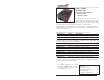
Cable Box - Cable Converter Box User Manual


10
S4TEF10xx-10x
24-Hour Technical Support: 1-800-260-1312 International: 00-1-952-941-7600
Operation
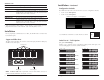
T1/E1 LEDs
Each T1/E1 link has a pair of LEDs embedded in the RJ-48 connector that
monitor the status of the link.
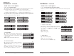
LNK LED (green)
On = T1/E1 link detected.
AIS LED (amber)
On = AIS (Alarm Indication Signal) detected. Failure of the device
connected to the T1/E1 port.
Fiber Network LEDs
Use the status LEDs next to the fiber port to monitor the media converter and
the fiber network connections.
LKF (fiber link)
On = Fiber link connection.
Flashing = Fiber network activity.
PWR (power)
On = Connection to external AC or DC power.
PWR
LKF
100Base-FX
TX
RX
4
3
2
1
LNKLNKLNKLNK AISAISAISAIS
fiber LEDs
T1/E1 LEDs
RS-232
11
techsupport@transition.com -- Click the “Transition Now” link for a live Web chat.
Operation -- Continued
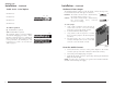
Remote Management Function
The S4TEF10xx-10x, can be remotely managed when connected via fiber cable
to a local C4TEF10xx-10x slide-in-module media converter that is installed in a
managed Transition Networks PointSystem™ chassis. The SNMP section
(below) lists the commands that can be used to monitor and manage a
networked S4TEF10xx-10x media converter at a remote location. For more
details, see the C4TEF10xx-10x user’s guide on-line at: www.transition.com.
SNMP
See the on-line documentation that comes with Transition Networks
FocalPoint™ software for applicable commands and usage.
Use SNMP at an attached terminal or at a remote location to monitor the media
converter by monitoring:
• Media converter power
• Fiber link status
• Copper link status for each T1/E1 (AIS, link)
• RS-232 status (speed, bits, parity, stop)
• AIS detected on fiber link
• All hardware switch settings
• Model #, serial #, PIC revision, HW revision, group string, connectors
Also, use SNMP to enter network commands that:
• Local and remote fiber loop-back
• Local and remote T1/E1 loop-back for each channel
• T1/E1 line options (DS1, DSX-1, J1, D1, AIS)
• RS-232 settings (speed, bits, parity, stop)
• T1/E1 monitor modes and loop-back modes
• Boot-load firmware (local unit only)
The local (auxiliary) factory maintenance interface via the RS-232 connector
supports:
• Switch selection for the RS-232 interface
• Access to all local and remote status information
• Perform all local and remote commands
• Operate at selected baud rates