
Datasheet


T
T
T
S
S
S
4
4
4
~
~
~
1
1
1
6
6
6
G
G
G
U
U
U
S
S
S
D
D
D
H
H
H
C
C
C
2
2
2
-
-
-
P
P
P
3
3
3
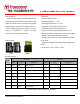
4~16GB microSDHC Class 2 Card + Reader P3
Transcend Information Inc.
3
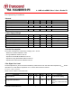
Bus Operating Conditions
• General
Parameter Symbol Min. Max. Unit Remark
Peak voltage on all lines -0.3 V
DD
+0.3 V
All Inputs
Input Leakage Current -10 10 µA
All Outputs
Output Leakage Current -10 10 µA
• Power Supply Voltage
Parameter Symbol Min. Max. Unit Remark
Supply voltage V
DD
2.7 3.6 V
Output High Voltage V
OH
0.75* V
DD
V I
OH
=-100uA@V
DD
Min.
Output Low Voltage V
OL
0.125* V
DD
V I
OL
=100uA@V
DD
Min.
Input High Voltage V
IH
0.625* V
DD
V
DD
+0.3 V
Input Low Voltage V
IL
V
SS
-0.3 0.25* V
DD
V
Power up time 250 ms From 0v to V
DD
Min.
• Current Consumption
The current consumption is measured by averaging over 1 second.
‧ Before first command: Maximum 15 mA
‧ During initialization: Maximum 100 mA
‧ Operation in Default Mode: Maximum 100 mA
‧ Operation in High Speed Mode: Maximum 200 mA
‧ Operation with other functions: Maximum 500 mA.
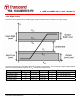
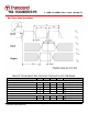
• Bus Signal Line Load
The total capacitance C
L
the CLK line of the SD Memory Card bus is the sum of the bus master capacitance C
HOST
, the bus
capacitance C
BUS
itself and the capacitance C
CARD
of each card connected to this line:
C
L
= C
HOST
+ C
BUS
+ Ν*C
CARD
Where N is the number of connected cards.
Parameter Symbol Min. Max. Unit Remark
Pull-up resistance R
CMD
R
DAT
10 100 kΩ To prevent bus floating
Bus signal line capacitance C
L
40 pF 1 card
C
HOST
+C
BUS
shall not exceed
30 pF