
Datasheet

T
T
T
S
S
S
4
4
4
~
~
~
1
1
1
6
6
6
G
G
G
U
U
U
S
S
S
D
D
D
H
H
H
C
C
C
2
2
2
-
-
-
P
P
P
3
3
3
4~16GB microSDHC Class 2 Card + Reader P3
Transcend Information Inc.
11
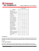
Register Information
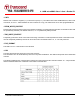
Within the card interface six registers are defined: OCR, CID, CSD, RCA, DSR and SCR. These can be accessed only
by corresponding commands (see Chapter 4.7). The OCR, CID, CSD and SCR registers carry the card/content specific
information, while the RCA and DSR registers are configuration registers storing actual configuration parameters.
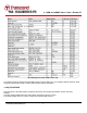
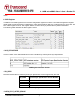
1. OCR register
The 32-bit operation conditions register stores the VDD voltage profile of the card. Additionally, this register
includes status information bits. One status bit is set if the card power up procedure has been finished. This register
includes another status bit indicating the card capacity status after set power up status bit. The OCR register shall be
implemented by the cards. The 32-bit operation conditions register stores the VDD voltage profile of the card. Bit 7 of
OCR is newly defined for Dual Voltage Card and set to 0 in default. If a Dual Voltage Card does not receive CMD8, OCR
bit 7 in the response indicates 0, and the Dual Voltage Card which received CMD8, sets this bit to 1.
Additionally, this register includes 2 more status information bits. Bit 31 - Card power up status bit, this status bit is
set if the card power up procedure has been finished. Bit 30 - Card capacity status bit, this status bit is set to 1 if card is
High Capacity SD Memory Card. 0 indicates that the card is Standard Capacity SD Memory Card. The Card Capacity
status bit is valid after the card power up procedure is completed and the card power up status bit is set to 1. The Host
shall read this status bit to identify a Standard or High Capacity SD Memory Card.
The OCR register shall be implemented by the cards.
OCR Register Definition