
Datasheet


T
T
T
r
r
r
a
a
a
n
n
n
s
s
s
c
c
c
e
e
e
n
n
n
d
d
d
4
4
4
0
0
0
-
-
-
P
P
P
i
i
i
n
n
n
I
I
I
D
D
D
E
E
E
F
F
F
l
l
l
a
a
a
s
s
s
h
h
h
M
M
M
o
o
o
d
d
d
u
u
u
l
l
l
e
e
e
T
T
T
S
S
S
1
1
1
2
2
2
8
8
8
M
M
M
~
~
~
1
1
1
6
6
6
G
G
G
D
D
D
O
O
O
M
M
M
4
4
4
0
0
0
V
V
V
-
-
-
S
S
S
Transcend Information Inc.
Ver 1.3
6
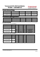
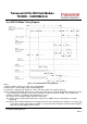
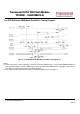
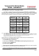
True IDE PIO Mode Read/Write Timing
Item
Mode
0
Mode
1
Mode
2
Mode
3
Mode
4
Mode
5
Mode
6
t
0
Cycle time (min)
1
600 383 240 180 120 100 80
t
1
Address Valid to -IORD/-IOWR setup (min)
70 50 30 30 25 15 10
t
2
-IORD/-IOWR (min)
1
165 125 100 80 70 65 55
t
2
-IORD/-IOWR (min) Register (8 bit)
290 290 290 80 70 65 55
t
2i
-IORD/-IOWR recovery time (min)
-- -- -- 70 25 25 20
t
3
-IOWR data setup (min)
60 45 30 30 20 20 15
t
4
-IOWR data hold (min)
30 20 15 10 10 5 5
t
5
-IORD data setup (min)
50 35 20 20 20 15 10
t
6
-IORD data hold (min)
5 5 5 5 5 5 5
t
6Z
-IORD data tristate (max)
2
30 30 30 30 30 20 20
t
7
Address valid to IOCS16 assertion (max)
4
90 50 40 N/A N/A N/A N/A
t
8
Address valid to IOCS16 released (max)
4
60 45 30 N/A N/A N/A N/A
t
9
-IORD/-IOWR to address valid hold
20 15 10 10 10 10 10
t
RD
Read Data Valid to IORDY active (min), if
IORDY initially low after tA
0 0 0 0 0 0 0
t
A
IORDY Setup time
3
35 35 35 35 35 N/A
5
N/A
5
t
B
IORDY Pulse Width (max)
1250
1250
1250
1250
1250
N/A
5
N/A
5
t
C
IORDY assertion to release (max)
5 5 5 5 5 N/A
5
N/A
5
Notes: All timings are in nanoseconds. The maximum load on -IOCS16 is 1 LSTTL with a 50 pF (40pF below
120nsec Cycle Time) total load. All times are in nanoseconds. Minimum time from -IORDY high to -IORD
high is 0 nsec, but minimum -IORD width shall still be met.
(1) t
0
is the minimum total cycle time, t
2
is the minimum command active time, and t
2i
is the minimum
command recovery time or command inactive time. The actual cycle time equals the sum of the actual
command active time and the actual command inactive time. The three timing requirements of t0, t
2
, and
t
2i
shall be met. The minimum total cycle time requirement is greater than the sum of t
2
and t
2i
. This means
a host implementation can lengthen either or both t
2
or t
2i
to ensure that t
0
is equal to or greater than the
value reported in the device’s identify device data.
(2) This parameter specifies the time from the negation edge of -IORD to the time that the data bus is
released by the device.
(3) The delay from the activation of -IORD or -IOWR until the state of IORDY is first sampled. If IORDY is
inactive then the host shall wait until IORDY is active before the PIO cycle can be completed. If the device
is not driving IORDY negated at t
A
after the activation of -IORD or -IOWR, then t
5
shall be met and t
RD
is
not applicable. If the device is driving IORDY negated at the time t
A
after the activation of -IORD or -IOWR,
then t
RD
shall be met and t5 is not applicable.
(4) t
7
and t
8
apply only to modes 0, 1 and 2. For other modes, this signal is not valid.
(5) IORDY is not supported in this mode.