
User's Manual

HARDWARE INSTALLATION
5
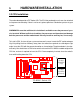
TS-ABX31
Transcend
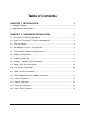
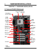
DIMM1 (64/72bit 168pin SDRAM Module)
DIMM2 (64/72bit 168pin SDRAM Module)
DIMM2 (64/72bit 168pin SDRAM Module)
COM1
AGP
PCI Slot1 (PCI1)
PCI Slot4 (PCI4)
PCI Slot2 (PCI2)
PCI Slot3 (PCI3)
ISA Slot1 (ISA1)
ISA Slot2 (ISA2)
Intel443ZXAGP Set
IntelPIIX4ChipSet
CR2032 3VLithium Cell
Primary IDE Connector
Second IDE Connector
Floppy Connector
2Mbit Flash (BIOS)
Multi-I/O&KeyboardController
FrequencyDIP Switch
PANEL
Panel Switch
IDE1IDE2
CASE-FAN
CPU-FAN
FDC
PCI1
PCI2
PCI3
PCI4
ISA1
ISA2
IrDA
Infrared Port
WOL
Wake On LAN
AGP
COMA
CMOS_CLR
HardwareMonitor
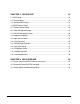
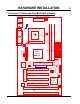
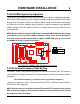
2.3 CPU Installation
The motherboard provides a ZIF Socket 370. The CPU that you bought must have a fan attached
to it to prevent overheating. If there is no fan on it, please purchase a fan before you turn on your
system.
WARNING! Be sure that sufficient air circulation is available across the processor’s pas-
sive heatsink. Without sufficient circulation, the processor could overheat and damage
both the processor and the motherboard. You may install an auxiliary fan, if necessary.
To install a CPU, first turn off your system and remove its cover. Locate the ZIF socket and open
it by first pulling the lever sideways away from the socket then upwards to a 90-degree right
angle. Insert the CPU with the correct orientation as shown below. The picture below is for refer-
ence only. You should have a CPU fan to cover the face of the CPU. With the added weight of the
CPU fan, no force is required to insert the CPU. Once completely inserted, close the socket
/
s
lever while holding down the CPU.
Socket 370
PS/2
T:Mouse B:Keyboard
USB
T:Port 1 B:Port 2
COM2
Printer
Parallel Port
ATX Power Connector
POWER-FANPWR-CONN
KB MOUSE
USB
COMB
Thermal Sensor
KB-AWK
Socket
370 CPU
(Bottom)
Notch
Socket
370 CPU
(Top)
Notch