TS-ABX31 Intel Socket 370 Celeron Series USER/S MANUAL Transcend Your Supplier, Your Partner, Your Friend.
User/s Notice This User/s Manual is designed to assist system manufacturers or end users to set up and install the motherboard. All information within this document has been carefully checked. However, Transcend Information, Inc. (hereinafter referred to as “Transcend”) carries no responsibility on liability to any error or inaccuracy which might occur in this manual, including the products and software mentioned in it.
Table of Contents CHAPTER 1 INTRODUCTION 1 1.1 Package Contents ............................................................................................................ 1 1.2 Specifications and Features ........................................................................................... 1 CHAPTER 2 HARDWARE INSTALLATION 3 2.1 Transcend TS-ABX31 Motherboard .................................................................... 3 2.2 Layout of Transcend TS-ABX31 Motherboard......................
CHAPTER 3 BIOS SETUP 16 3.1 BIOS Setup ....................................................................................................................... 16 3.2 The Main Menu ................................................................................................................ 16 3.3 Standard CMOS Setup ................................................................................................... 18 3.4 BIOS Features Setup ...............................................................
1 INTRODUCTION CHAPTER 1 INTRODUCTION 1.1 Package Contents This motherboard package contains the following items. If you discover any damaged or missing items, please contact your retailer. 1 - TS-ABX31 motherboard 2 - CD-ROM 3 - One FDD cable, one IDE cable 4 - User’s Manual 1.
INTRODUCTION - Support PS/2 mouse and PS/2 keyboard - Support IrDA port - Support 2 Universal Serial Bus Ports • Award BIOS - Support Plug-and-Play - Support ACPI, DMI, Green Feature • Wake Up Features - PS/2 mouse and keyboard Wake Up - Support Wake-on-LAN function - Remote Ring Wake Up • PCB Dimensions - ATX form factor, 4-layer PCB, 17.3cm x 30.5cm (6.
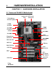
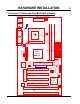
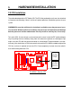
HARDWARE INSTALLATION 3 CHAPTER 2 HARDWARE INSTALLATION 2.
HARDWARE INSTALLATION 4 2.
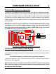
HARDWARE INSTALLATION 5 2.3 CPU Installation The motherboard provides a ZIF Socket 370. The CPU that you bought must have a fan attached to it to prevent overheating. If there is no fan on it, please purchase a fan before you turn on your system. WARNING! Be sure that sufficient air circulation is available across the processor’s passive heatsink. Without sufficient circulation, the processor could overheat and damage both the processor and the motherboard. You may install an auxiliary fan, if necessary.
HARDWARE INSTALLATION 6 2.4 66/100MHz System Configuration The jumper 2 (JP2) allows you to set FSB (Front Side Bus) to be 66 or 100MHz configuration. When you set FSB to 66MHz, you can select the system bus frequency from 66MHz to 83.3MHz through “CPU Host Clock (CPU/PCI)” of “Chipset Features Setup” in BIOS (Please refer to page 26).
HARDWARE INSTALLATION 7 CPU Internal SW1 Frequency JP2 Freq.-Ratio 1 2 3 4 333/500MHz 66/100MHz x 5.0 ON OFF OFF ON 366/550MHz 66/100MHz x 5.5 ON OFF OFF OFF 400/600MHz 66/100MHz x 6.0 OFF ON ON ON 433/650MHz 66/100MHz x 6.5 OFF ON ON OFF 466/700MHz 66/100MHz x 7.0 OFF ON OFF ON 500/750MHz 66/100MHz x 7.
HARDWARE INSTALLATION 8 2.6 Memory Configuration This motherboard must be installed with DIMM (Dual Inline Memory Module). The DIMMs must be 3.3 Volt synchronous DRAM modules. It also supports ECC (Error Checking and Correcting). IMPORTANT: Memory speed setup is required through “Auto Configuration“ in BIOS Chipset Features Setup.
HARDWARE INSTALLATION 9 2.7 Keyboard Wake Up (3-pin KB-AWK) This function disables or enables you to use the keyboard to power up the system. Set this jumper to “Enable” if you wish to use your keyboard to power up your computer.
HARDWARE INSTALLATION 10 2.9 Floppy Disk Drive Connector (34-pin FDC) This connector supports the provided floppy disk drive ribbon cable. After connecting the single end to the board, connect the two plugs on the other end to the floppy drives.
HARDWARE INSTALLATION 11 2.11 Wake-on-LAN Connector (3-pin WOL) This connector connects to LAN cards with a Wake-on-LAN output. The system can be powered up when a wakeup packet or signal is received from the LAN card. NOTE:This function requires that the Wake-on-LAN Power Up Control is set to “Enabled” and that your system has an ATX power supply with at least 720mA +5V standby power.
HARDWARE INSTALLATION 12 2.13 Panel Connectors Power LED Lead (3-pin KEYLOCK) This 3-pin connector attaches to the power LED. Pin1 : +5V Pin2 : NC Pin3 : GND Keylock Lead (2-pin KEYLOCK) Use the keylock to enable or disable the keyboard. Pin4 : KEYLOCK Pin5 : GND Speaker Lead (4-pin SPEAKER) This 4-pin connector connects to the case-mounted speaker. Pin7 : +5V Pin8 : GND Pin9 : NC Pin10 : SPK Suspend Mode LED Lead (2-pin S_LED) The S_LED will light when the suspend mode works.
HARDWARE INSTALLATION 13 Software Power-Off Lead (2-pin SOFT_OFF) Attach the SOFT_OFF Switch of the panel to this connector.
HARDWARE INSTALLATION 14 2.15 External Connectors There are 5 kinds of external connectors on the motherboard. 1. PS/2 Mouse Connector (6-pin MOUSE) The onboard PS/2 mouse connector is a 6-pin Mini-Din connector marked “MOUSE” The view angle of drawing shown here is from back panel of the housing. 2. PS/2 Keyboard Connector (6-pin KB) The onboard PS/2 keyboard connector is a 6-pin Mini-Din connector marked “KB”. The view angle of drawing shown here is from back panel of the housing. 3.
HARDWARE INSTALLATION 15 2.16 Clear CMOS Jumper (3-pin JP4) To clear the CMOS data, you should turn off your computer power and short the pin1 and pin2 of JP4.
BIOS SETUP 16 CHAPTER 3 BIOS SETUP 3.1 BIOS Setup Award BIOS has a built-in Setup program that allows users to modify the basic system configuration. This information is stored in CMOS RAM. So it can retain the Setup information when the power is turned off. When the battery of CMOS fails, it will cause the data lost. When it happens, you should set up your configuration parameters again after replacing the battery. 3.2 The Main Menu As you turn on or reboot the system, the BIOS is immediately activated.
17 BIOS SETUP F1 General help, only for Status Page Setup Menu and Option Page Setup Menu F2 Change color from total 16 colors F2 Shift + F2 to select color forward to select color backward F3 Calendar, only for Status Page Setup Menu F5 Restore the previous CMOS value from CMOS, only for Option Page Setup Menu F6 Load the default CMOS RAM value from BIOS default table, only for Option Page Setup Menu F7 Load the default F10 Save all the CMOS changes, only for Main Menu The Following is a b
BIOS SETUP 18 • SUPERVISOR / USER PASSWORD Change, set, or disable a password. In some BIOS versions that allow separate user and supervisor passwords, only the supervisor password permits access to Setup. The user password generally allows only power-on access. • IDE HDD AUTO DETECTION Automatically detect and configure IDE hard disk parameters. • SAVE & EXIT SETUP Save settings in nonvolatile CMOS RAM and exit Setup. • EXIT WITHOUT SAVING Abandon all changes and exit Setup. 3.
BIOS SETUP 19 1. Match the specifications of your installed IDE hard drive(s) with the preprogrammed values for drive type 1 through 45. 2. Select “USER” and enter values into each drive parameter field. 3. Use the “IDE HDD AUTO DETECTION” function in Main Menu. Here are the brief explanations of drive specifications. * TYPE : The BIOS contains a table of pre-defined drive types.
BIOS SETUP 20 • Drive A / Drive B Select the correct specifications for the diskette drive(s) installed in the computer. - None : No diskette drive installed - 360K, 5.25 in : 5-1/4 inch PC-type standard drive; 360 kilobyte capacity - 1.2M, 5.25 in : 5-1/4 inch AT-type high-density drive; 1.2 megabyte capacity - 720K, 3.5 in : 3-1/2 inch double-sided drive; 720 kilobyte capacity - 1.44M, 3.5 in : 3-1/2 inch double-sided drive; 1.44 megabyte capacity - 2.88M, 3.5 in : 3-1/2 inch double-sided drive; 2.
21 BIOS SETUP 3.4 BIOS Features Setup This “BIOS FEATURES SETUP” option allows you to improve your system performance and set up system features according to your preference. • Virus Warning When the function is enabled, you will receive a warning message if a program (specifically, a virus) attempts to write to the boot sector or the partition table of the hard disk drive. You should then run an anti-virus program. Keep in mind that this feature protects the boot sector only, not the entire hard drive.
BIOS SETUP 22 • CPU L2 Cache ECC Checking Select “Enabled” to make sure the data accuracy. • Quick Power On Self Test Select “Enabled” to reduce the amount of time required to run the Power-On Self-Test (POST). A quick POST skips certain steps. We recommend that you normally disable quick POST. It’s better to find a problem during POST than to lose data during your work. • Boot Sequence The original IBM PCs load the DOS operating system from drive A (floppy disk).
23 BIOS SETUP • Typematic Rate (Chars / Sec) When the typematic rate setting is enabled, you can select a typematic rate (the rate at which character repeats) when you hold down a key of 6, 8, 10,12, 15, 20, 24 or 30 characters per second. • Typematic Delay (Msec) When the typematic delay setting is enabled, you can select a typematic delay (the delay before key strokes begin to repeat) of 250, 500, 750 or 1000 milliseconds.
BIOS SETUP 24 each section of memory separately. Many system designers hardwire shadowing of the system BIOS and eliminate a System BIOS Shadow option. Video BIOS shadows into memory area C0000-C7FFF. The remaining areas shown on the “BIOS Features Setup” screen may be occupied by other expansion card firmware. If an expansion peripheral in your system contains ROM-based firmware, you need to know the address range the ROM occupies to shadow it into the correct area of RAM. 3.
25 BIOS SETUP • SDRAM RAS-to-CAS Delay This controls the latency between SDRAM active command and the read/write command. Leave on default setting. • SDRAM RAS Precharge Time This controls the idle clocks after issuing a precharge command to SDRAM. Leave on default setting. • SDRAM CAS Latency Time This controls the SDRAM performance, default is 3 clocks. If your SDRAM DIMM specification is 2 CAS latency, change 3 to 2 for better performance.
BIOS SETUP 26 • Memory Hold At 15M-16M Enabling this feature reserves memory address space from 15MB to 16MB to ISA expansion cards that specifically require this setting. This makes the memory from 15MB and up unavailable to the system. Expansion cards can only access memory up to 16MB. The default is “Disabled”. • Passive Release ISA access speed is lower than PCI access speed. While power on, the ISA interface would release master bus control.
27 BIOS SETUP 3.6 Power Management Setup The Power Management Setup allows you to configure your system to save energy most effectively while operating in a manner consistent with your own style of computer use. • ACPI function This item allows you to enable/disable the Advanced Configuration and Power Management (ACPI). The choice: Enabled, Disabled. • Power Management This category allows you to select the type (or degree) of power saving and is directly related to the following modes. 1. Doze Mode 2.
BIOS SETUP 28 3. Max. Power Saving : Maximum power management mode. Inactivity period is defined as below. Doze Mode = 1 min. Standby Mode = 1 min. Suspend Mode = 1 min. HDD Power Down = 1 min. 4. User Defined : Allow you to set each mode individually. Select time-out period for each mode shown above. • PM Control by APM When enabled, an Advanced Power Management device will be activated to enhance the Max. Power Saving mode and stop the CPU internal clock. If the Max.
29 BIOS SETUP • Standby Mode After the selected period of system inactivity (1 minute to 1 hour), the fixed disk drive and the video shut off while all other devices still operate at full speed. • Suspend Mode After the selected period of system inactivity (1 minute to 1 hour), all devices except the CPU shut off. • HDD Power Down After the selected period of system inactivity (1 to 15 minutes), the hard disk drive powers down while all other devices remain active.
BIOS SETUP IRQ[3-7, 9-15], NMI 30 To enable or disable the detection of IRQ 3-7, IRQ 9-15 or NMI interrupt events for powering down state transition. These items enable or disable the detection of IDE, floppy, Primary IDE 0 serial and parallel port activities for powering down state Primary IDE 1 transition.Actually it detects the read/write to/from I/O ports. Secondary IDE0 Secondary IDE1 Floppy Disk Serial Port Parallel port 3.
BIOS SETUP 31 • Resource Controlled by The Award Plug and Play BIOS can automatically configure all the boot and Plug and Play(PnP) compatible devices. If you select “Auto”, all the interrupt request (IRQ) and DMA assignment fields disappear, as the BIOS automatically assigns them. The choice: Auto and Manual. • Reset Configuration Data Normally, you leave this field “Disabled”.
BIOS SETUP 32 3.8 Integrated Peripherals This option will load the default BIOS values. Choose the option and the following message appears. • IDE HDD Block Mode The item means HDD access uses over one cycle method for improving HDD performance. If the HDD supports this function, choose” Enabled”. • IDE Primary/Secondary Master/Slave PIO The four IDE PIO (Programmed Input/Output) fields let you set a PIO mode (0-4) for each of the four IDE devices that the onboard IDE interface supports.
33 BIOS SETUP • On Chip IDE Primary / Secondary PCI IDE The chipset contains a PCI IDE interface which supports two IDE channels. Select “Enabled” to activate the first and/or second IDE interface. Select “Disabled” to deactivate an interface, if you install a primary and/or secondary add-in IDE interface. • USB Keyboard Support Select “Enabled” if you have a USB keyboard. • Init Display First This item allows you to decide to activate PCI Slot or AGP first.
BIOS SETUP 34 • Onboard Serial Port 1 Select an address and the corresponding interrupt for each of the first and second serial ports. The Choice: 3F8/IRQ4, 2F8/IRQ3, 3E8/IRQ4, 2F8/IRQ3, Disabled, Auto. • Onboard Serial Port 2 The second serial port shares resources (address and IRQ) with IrDA.
35 BIOS SETUP 3.9 Supervisor Password This option will set the password to prevent others from making changes to your system. Password prevents unauthorized use of your computer. If you set a password, the system prompts for the correct password before you boot or access to “Setup” To set a password: 1. At the prompt, type your password. Your password can be up to 8 alphanumeric characters. When you type the characters, they appear as asterisks on the password screen box. 2.
BIOS SETUP 36 3.10 User Password This option will set the password to prevent others from making changes to your system when accessed by POWER ON. This operation is same as SUPERVISOR PASSWORD. 3.11 IDE HDD Auto Detection Use the BIOS utility to detect the HDD type automatically. Press “Y” to accept, “N” to reject, and “ESC” to the next detection.
37 BIOS SETUP 3.12 Save & Exit Setup Save the setting and exit the BIOS utility. 3.13 Exit Without Saving Abort the current change and exit the BIOS utility.
BIOS SETUP 38 3.14 Load BIOS Defaults NOTE: This option allows you to load the troubleshooting default values permanently stored in the BIOS ROM. These default settings are non-optimal and disable all high performance features. 3.15 Load Setup Defaults This option allows you to load the default values to the system configuration fields. These default values are the optimized configuration settings for the system.
39 BIOS UPGRADE 4.1 How to Check Your BIOS File Name and Version Please turn on PC first, the screen will display as follows : TRANSCEND MODULAR BIOS : ABX3A-V10 You can see a description shows at the third line. ABX3A - V10 BIOS Version 1.0 (V11 for Version 1.1) ( You can upgrade to neewer version if your BIOS version is older than this version.) BIOS File Name (Make sure the first 5 charactors c must be the same as your own version, if you want to upgrade u your BIOS.) 4.
BIOS UPDATE 40 Step 2: Make a System Disk - Put a clean 3.5" disk in Drive A MS-DOS : Key in FORMAT A:/S and press [Enter]. Windows O/S : Select the icon of [My Computer] Click [3.5" Floppy (A:)] Select [File/Format] from Command Bar Under Format 3.5 Floppy (A:) Menu select Format type = Full item and Other Options = Copy system files Click [Start] button Step 3: Download the updated BIOS EXE file from the web site to a floppy disk. (Ref 4.1 and 4.2) Step 4: Execute the download file to decompress it.