
Compact Flash Card Specification Sheet

T
T
T
S
S
S
2
2
2
G
G
G
~
~
~
8
8
8
G
G
G
C
C
C
F
F
F
2
2
2
6
6
6
6
6
6
266X CompactFlash Card
Transcend Information Inc.
59
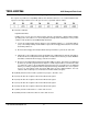
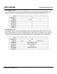
¾ Word 1: Default Number of Cylinders
This field contains the number of translated cylinders in the default translation mode. This value will be the
same as the number of cylinders.
¾ Word 3: Default Number of Heads
This field contains the number of translated heads in the default translation mode.
¾ Word 6: Default Number of Sectors per Track
This field contains the number of sectors per track in the default translation mode.
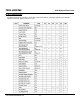
¾ Words 7-8: Number of Sectors per Card
This field contains the number of sectors per CompactFlash Storage Card. This double word
value is also the first invalid address in LBA translation mode.
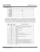
¾ Words 10-19: Serial Number
This field contains the serial number for this CompactFlash Storage Card and is right justified and padded
with spaces (20h).
¾ Word 22: ECC Count
This field defines the number of ECC bytes used on each sector in the Read and Write Long commands.
This value shall be set to 0004h.
¾ Words 23-26: Firmware Revision
This field contains the revision of the firmware for this product.
¾ Words 27-46: Model Number
This field contains the model number for this product and is left justified and padded with spaces (20h).
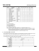
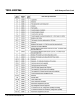
¾ Word 47: Read/Write Multiple Sector Count
Bits 15-8 shall be the recommended value of 80h or the permitted value of 00h. Bits 7-0 of this word define
the maximum number of sectors per block that the CompactFlash Storage Card supports for Read/Write
Multiple commands.
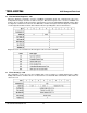
¾ Word 49: Capabilities
Bit 13: Standby Timer
If bit 13 is set to 1 then the Standby timer is supported as defined by the IDLE command
If bit 13 is set to 0 then the Standby timer operation is defined by the vendor.
Bit 11: IORDY Supported
If bit 11 is set to 1 then this CompactFlash Storage Card supports IORDY operation.
If bit 11 is set to 0 then this CompactFlash Storage Card may support IORDY operation.
Bit 10: IORDY may be disabled
Bit 10 shall be set to 0, indicating that IORDY may not be disabled.
Bit 9: LBA supported
Bit 9 shall be set to 1, indicating that this CompactFlash Storage Card supports LBA mode addressing.
CF devices shall support LBA addressing.
Bit 8: DMA Supported If bit 8 is set to 1 then Read DMA and Write DMA commands are supported. Bit 8
shall be set to 0. Read/Write DMA commands are not currently permitted on CF cards.
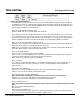
¾ PIO Data Transfer Cycle Timing Mode
The PIO transfer timing for each CompactFlash Storage Card falls into modes that have unique
parametric timing specifications. The value returned in Bits 15-8 shall be 00h for mode 0, 01h for mode 1,
or 02h for mode 2. Values 03h through FFh are reserved.