
Installation Guide

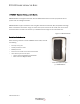
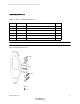
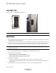
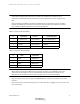
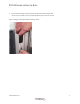
Table Of Contents
- Table 1: Revision History
- DR5000 Reader Installation Guide
- Mounting Options
- Figure 1-3 Figure 1-3 DR5000 Mounting Options
- Detailed Installation
- 1 For installations without a trim plate, use the mounting plate as a guide to drill mounting holes and cable route opening in the mounting surface.
- 2 Route cable through opening or to the single gang box, see wiring tables on step 6.
- 3 Install the trim plate if applicable.
- 4 Install the mounting plate.
- 5 Connect the wires to the terminal blocks. Refer to tables 2 and 3 for wiring connections.
- Table 1-2: Figure 1-5 TB1 Connections
- Table 1-3: Figure 1-6 TB2 Connections
- 6 Plug the terminal block(s) onto the pins of the DR5000 Reader; and the terminal blocks in the proper locations.
- 7 Place the reader just above the mounting plate, and then slide down to engage the tab into notch on the back of the reader.
- 8 Secure reader using the tamper resistant security screw (3/32" tamper hex).
- Figure 1-4 Figure 1-8 Tamper Resistant Security Screw
- Reader Configuration
- Reader Testing
- Troubleshooting
- Specifications

DR5000 READER INSTALLATION GUIDE
403-003-001 Rev A
7
READER CONFIGURATION
DR5000 Readers can interface to Transact SA3032 Access Controllers using a serial RS-485 connection. The
readers are configured the same as the DR4XXXX series and the legacy SE3-CS and SE3-CSPP readers. When
prompted for serial reader(s), select either 1 - SE3-CS/CSPP/RDR100 if only one reader is being installed, or 2 -
SE3-CS/CSPP/RDR100 if two readers are being installed.
DR5000 Readers can interface to 3rd party access control panels using the industry standard Wiegand
interface. Refer to the 3rd party access control documentation for configuration instructions.
Tamper Operation
The SA3032 door controller continually polls the reader over RS-485 interface. If the reader stops responding to
polls, a reader offline condition is detected.
The DR5000 Readers have an optical tamper sensor on the back that senses if the reader is removed from the
mounting surface or trim plate. This tamper condition is reported on the additional TAMPER output signal (TB2-
4).
READER TESTING
DR5000 Readers do not require maintenance. Test the reader monthly to verify operation.
Test the Card Read Range
1 Hold a valid card approximately 1.5" parallel to reader face.
2 Verify that the Green VALID annunciator turns on.
Test the Card Reader
• Tapping a valid card will turn on the green VALID annunciator
• Tapping an invalid card will turn on the red DENIED annunciator
• If tones are enabled, tapping a valid card will generate a long beep
• If tones are enabled, tapping an invalid card will generate a warble sound
• The key pad, if equipped, should generate a tone after pressing each of the keys
Note: The Transact logo located near the bottom right of the reader illuminates when power is
supplied to the reader.