
Installation Guide

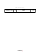
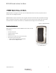
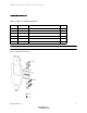
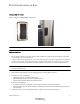
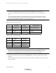
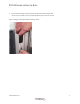
Table Of Contents
- Table 1: Revision History
- DR5000 Reader Installation Guide
- Mounting Options
- Figure 1-3 Figure 1-3 DR5000 Mounting Options
- Detailed Installation
- 1 For installations without a trim plate, use the mounting plate as a guide to drill mounting holes and cable route opening in the mounting surface.
- 2 Route cable through opening or to the single gang box, see wiring tables on step 6.
- 3 Install the trim plate if applicable.
- 4 Install the mounting plate.
- 5 Connect the wires to the terminal blocks. Refer to tables 2 and 3 for wiring connections.
- Table 1-2: Figure 1-5 TB1 Connections
- Table 1-3: Figure 1-6 TB2 Connections
- 6 Plug the terminal block(s) onto the pins of the DR5000 Reader; and the terminal blocks in the proper locations.
- 7 Place the reader just above the mounting plate, and then slide down to engage the tab into notch on the back of the reader.
- 8 Secure reader using the tamper resistant security screw (3/32" tamper hex).
- Figure 1-4 Figure 1-8 Tamper Resistant Security Screw
- Reader Configuration
- Reader Testing
- Troubleshooting
- Specifications

DR5000 READER INSTALLATION GUIDE
403-003-001 Rev A
5
Note: Install in accordance with the National Electrical Code (NEC), ANSI/NFPA 70, and local
codes. When using third-party equipment, to maintain UL compliance, the readers must be
connected to a UL294 listed access control panel or power supply with an output voltage of 6-24
VDC.
When connecting the DR5000 to the Transact SA3000 Access Control System, typically only TB1 is
installed. The SA3000 Door Controller provides power (VCC and GND). Communication is provided
by connected the RS-485+/RS-485- to the corresponding signals.
Table 1-2: Figure 1-5 TB1 Connections
Table 1-3: Figure 1-6 TB2 Connections
Note: To maintain UL compliance, install only 1 wire in each terminal block opening of the DR5000
Reader. When connecting two DR5000s to a single Door Controller, one of DR5000s must have a
jumper wire connecting pin 3 to pin 4 on terminal block TB2. This identifies the address on the
arbitrated bus. Software detects the jumper and responds to the correct poll messages.
6 Plug the terminal block(s) onto the pins of the DR5000 Reader; and the terminal blocks in the proper
locations.
7 Place the reader just above the mounting plate, and then slide down to engage the tab into notch on the
back of the reader.
# Description Transact 3rd Party Wiegand
1 V+ (power) VCC Door controller Power Voltage Input (+)
2 GND Door controller Ground
3 RS-485 + Door controller D0 Data
4 RS-485 - Door controller D1 CLK
# Label Description
1 GLED GREEN LED
2 RLED RED LED input
3 BEEP Beeper input
4 TMPR Tamper output