
Installation Guide
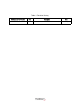
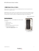
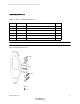
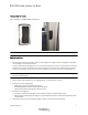
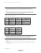
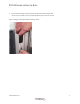
Table Of Contents
- Table 1: Revision History
- DR5000 Reader Installation Guide
- Mounting Options
- Figure 1-3 Figure 1-3 DR5000 Mounting Options
- Detailed Installation
- 1 For installations without a trim plate, use the mounting plate as a guide to drill mounting holes and cable route opening in the mounting surface.
- 2 Route cable through opening or to the single gang box, see wiring tables on step 6.
- 3 Install the trim plate if applicable.
- 4 Install the mounting plate.
- 5 Connect the wires to the terminal blocks. Refer to tables 2 and 3 for wiring connections.
- Table 1-2: Figure 1-5 TB1 Connections
- Table 1-3: Figure 1-6 TB2 Connections
- 6 Plug the terminal block(s) onto the pins of the DR5000 Reader; and the terminal blocks in the proper locations.
- 7 Place the reader just above the mounting plate, and then slide down to engage the tab into notch on the back of the reader.
- 8 Secure reader using the tamper resistant security screw (3/32" tamper hex).
- Figure 1-4 Figure 1-8 Tamper Resistant Security Screw
- Reader Configuration
- Reader Testing
- Troubleshooting
- Specifications

DR5000 READER INSTALLATION GUIDE
403-003-001 Rev A
9
SPECIFICATIONS
Physical Size: 1.45"W x 4.0"H x 0.75"D
Input Power: 6 - 24VDC 1.4W max
Temperature Range: -35 to +66 Celsius
Suitable for indoor and outdoor use
Wiegand Signal
Specifications:
Inputs (RED LED, GRN LED, BEEP
• 0 - 5.5V maximum
• Active when < 2.5V (driver must be able to sink at least 1mA)
Outputs (D0, D1, TAMPER):
• Open-drain outputs, max sink current 100mA
• Internal 10K pullup to 5V
• Tamper output polarity is configurable
UL294 Performance Levels: Line Security: I
Attack: I
Endurance: IV
Standby Power: I