
Installation Guide
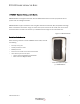
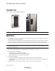
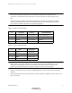
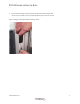
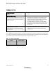
Table Of Contents
- Table 1: Revision History
- DR5000 Reader Installation Guide
- Mounting Options
- Figure 1-3 Figure 1-3 DR5000 Mounting Options
- Detailed Installation
- 1 For installations without a trim plate, use the mounting plate as a guide to drill mounting holes and cable route opening in the mounting surface.
- 2 Route cable through opening or to the single gang box, see wiring tables on step 6.
- 3 Install the trim plate if applicable.
- 4 Install the mounting plate.
- 5 Connect the wires to the terminal blocks. Refer to tables 2 and 3 for wiring connections.
- Table 1-2: Figure 1-5 TB1 Connections
- Table 1-3: Figure 1-6 TB2 Connections
- 6 Plug the terminal block(s) onto the pins of the DR5000 Reader; and the terminal blocks in the proper locations.
- 7 Place the reader just above the mounting plate, and then slide down to engage the tab into notch on the back of the reader.
- 8 Secure reader using the tamper resistant security screw (3/32" tamper hex).
- Figure 1-4 Figure 1-8 Tamper Resistant Security Screw
- Reader Configuration
- Reader Testing
- Troubleshooting
- Specifications

DR5000 READER INSTALLATION GUIDE
8
403-003-001 Rev A
TROUBLESHOOTING
If mixing DR5000 and DR4xxx readers in a 2 reader configuration connected to a single Door Controller, one of
the readers must always be configured with a jumper. This identifies which reader will answer polls on address
1. The reader choice is arbitrary just as long as only one reader has the jumper.
Power Indicator is off - If the Power indicator behind
the Transact logo remains off when power is
applied:
• Verify that the proper voltage is being supplied (TB1-1 = +V, TB1- 2
= GND)
Red annunciator blinking - DR5000 Readers Red
annunciator flashes (approximately 1 second rate)
when communication is lost with the SA3000 Door
Controller Unit. If the Red annunciator is flashing,
check the following:
• Verify the SA3000 Controller Unit has been properly configured for
Serial Readers. This configuration is made by selecting SE3- CS/
CSPP/RDR100 in the Serial Reader(s) option. Reference the
SA3000 Door Access Control System Installation Guide (DOC#
988) in the Controller Unit Configuration (page 28)
• If two DR5000 Readers are installed and operating in RS-485
mode, verify one reader has TB2-3 jumpered to TB2-4, verify the
wiring between the reader and the Door Controller board in the
SA3000 System
No annunciation after card tap - One annunciator
always turns on after a contactless card is tapped. If
no annunciator turns on, the Reader may have
corrupted software or the card may be damaged or
not programmed.
• Check software integrity, cycle power to the Reader, the annunci-
ators should turn ON and OFF in sequence, along with four beeps,
indicating the Reader has successfully executed its power-up
initialization code
Table 1-4: Jumper Configuration
Reader Jumper Position
DR4xxx TB1-1 to TB1-5
DR5000 TB2-3 to TB2-4