
User's Manual
M-FALCON2 Rev B
Copyright © 2000 Trango Systems, Inc. (All rights reserved)
24
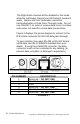
VRX5900 Receiver Inputs/Outputs & Controls:
1. POWER INPUT
Accepts a 6-9 Vdc power source such as the standard 7
Vdc adapter (Trango part number PT07800-1), or an
optional battery. The nominal current draw is 450
milliamperes. If using an adapter from a third party, use
a well-regulated 6-9Vdc/500mA output supply.
2. ALARM OUTPUTS
These are dry (no voltage) contact relay outputs that can
sink 1 ampere at 40 V AC/DC. When the corresponding
transmitter alarm input closes or opens, this output will
close and open as well. Consider these outputs mirrors
of the transmitter alarm inputs. These outputs are
independent and can be used to turn on peripheral
devices such as video recorders and audible alarms.
3/4. RIGHT & LEFT AUDIO OUTPUTS
Designed to mate to a standard RCA male connector,
this provides a 1.5 Volt peak-to-peak audio output and
should be terminated in a minimum 600Ω load, as is
found in most “line in” audio inputs.
5. STEREO/ALARM SWITCH
When this switch is in the “R Audio On” position, stereo
audio transmission is enabled. This permits the
transmission of stereo audio with no data or alarms.
When it is in the “Alm/Data Mode On” position, alarm
transmission is enabled. If Data Pass-Through mode is
enabled through the TrangoLink software, the switch
must be set to the “Alm/Data Mode On” position.
6. DATA INTERFACE
When connected to a personal computer via the optional
CBLDAT-1 interface cable, this input accepts serial