
User's Manual

M-FALCON2 Rev B
Copyright © 2000 Trango Systems, Inc. (All rights reserved)
12
Transmitter Operation
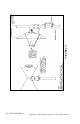
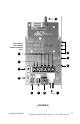
Figure 2 shows the interior of the VTX5900 transmitter and the
functions of each control and input/output. Each control is
described in greater detail below. This card is encased in a NEMA
4X rated aluminum/powdercoat enclosure. Do not remove the card
from the enclosure.
IMPORTANT NOTE: The transmitter uses a non-
standard jack to connect to the transmitter antenna.
Any modification to this jack may void the user’s
authority to operate the equipment and will void the
manufacturer’s warranty.
CAUTION
DO NOT APPLY POWER TO THE TRANSMITTER
WITHOUT THE ANTENNA SECURELY ATTACHED.
DO NOT APPLY VOLTAGE TO THE ALARM PINS.
DAMAGE TO THE UNIT MAY RESULT.
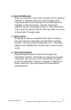
1. Power
2. Alarm 1/2 inputs
3. Right audio input
4. Left audio input
5. Stereo/Alarm switch
6. Data
7. Video input
8. Toggle/Standby
9. Status LED
10. Channel LEDs
11. Antenna connector
12. Header for use with optional LC-485/422
(LC485/422 used to transmit simplex data for control.)