Falcon PLUS™ SERIES 5.
(This Page Intentionally Left Blank) M-FALCON2 Rev B Copyright © 2000 Trango Systems, Inc.
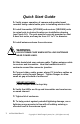
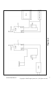
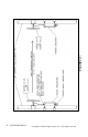
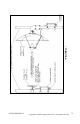
Quick Start Guide 1• Verify proper operation of camera and monitor/event recorder using coaxial cable prior to installing wireless link. 2• Install transmitter (VTX5900) and receiver (VRX5900) units to a steel pole in desired location per installation drawing (see Figure 1A). The pole must be securely mounted so that it does not move, and may be from 1.5” to 3” in diameter. 3• Install antennas above the enclosures. WARNING USE EXTREME CARE WHEN INSTALLING ANTENNAS NEAR POWER LINES.
CAUTION DO NOT APPLY POWER TO THE TRANSMITTER UNLESS THE ANTENNA IS CONNECTED. PERMANENT DAMAGE MAY RESULT. M-FALCON2 Rev B Copyright © 2000 Trango Systems, Inc.
Your Trango Wireless Video System Congratulations on choosing Trango Systems, Inc. to fulfill your wireless video needs. Unpack your system carefully. If any items are missing, notify your sales representative. If an item appears to be damaged from shipment, replace it in its packing material and notify the shipper. Save the packaging for further storage of the equipment. Service: If the unit ever needs repair service, contact a Trango Systems, Inc.
2) Increase the separation between the affected equipment and the receiver; 3) Connect the affected equipment to an outlet on a different circuit from that which the receiver is connected to; 4) Consult the dealer and/or experienced radio/TV technician for help. VTX5950: #NCYVTX5950 VTX5900: # NCYVTX5900 CANADA: VTX5900: 29451031885 VRX5900: 29451031885A IMPORTANT NOTE: Intentional or unintentional changes or modifications not expressly approved by the party responsible for compliance must not be made.
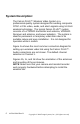
System Description: The Falcon PLUS™ Wireless Video System is a professional quality system designed for sending composite NTSC or PAL video, audio, and alarm signals using 5.8 GHz wireless technology. The typical Falcon PLUS™ system consists of a VTX5900 transmitter and antenna, VRX5900 Receiver and antenna, and power adapters. The system is ideal for permanent or temporary video links due to its portable nature and easy installation. It is not designed for operation while in motion.
• Figure 1a• M-FALCON2 Rev B Copyright © 2000 Trango Systems, Inc.
• FIGURE 1b • 8 M-FALCON2 Rev B Copyright © 2000 Trango Systems, Inc.
• FIGURE 1c • M-FALCON2 Rev B Copyright © 2000 Trango Systems, Inc.
• FIGURE 1d • 10 M-FALCON2 Rev B Copyright © 2000 Trango Systems, Inc.
Installation: The Falcon PLUS™ system is factory-configured for operation on channel 1 with right and left audio operational. To obtain the best picture quality and transmission distance, the following rules of thumb should be followed: 1) Mount the transmitter and receiver antennas above human and mechanical traffic, the higher the better. A 10 foot 2 3/8” diameter steel mast on top of a building is typical. Make sure that the mast is well grounded to earth ground with an 8 AWG or larger wire.
Transmitter Operation F igure 2 shows the interior of the VTX5900 transmitter and the functions of each control and input/output. Each control is described in greater detail below. This card is encased in a NEMA 4X rated aluminum/powdercoat enclosure. Do not remove the card from the enclosure. IMPORTANT NOTE: The transmitter uses a nonstandard jack to connect to the transmitter antenna.
11 Use with dry (no voltage) contact closures only. 10 2 8 1 9 5 12 3 4 6 7 • FIGURE 2• M-FALCON2 Rev B Copyright © 2000 Trango Systems, Inc.
VTX5900 Transmitter Inputs & Controls: 1. POWER INPUT Accepts a 6-12 Vdc power source such as the standard 7 Vdc adapter (Trango part number PT07800-1), or an optional battery. The nominal current draw is 200 milliamperes. If using an adapter from a third party, use a well-regulated 300 mA minimum output supply. Do not use the PT07800-1 to power a camera or video distortion may occur. 2. ALARM INPUTS These inputs are used to send alarm signals to the receiver.
6. DATA INTERFACE When connected to a personal computer via the optional CBLDAT-1 interface cable, this input accepts serial commands that control settings in the transmitters not available on the front panel. See the TrangoLink software section and program help for more information. This is also the input for the RS-232 user data to be sent in Data Pass-Through mode. 7. VIDEO INPUT Designed to mate to a standard BNC male connector, this input accepts 1Vpp video in both NTSC and PAL formats.
9/10. STATUS/CHANNEL LEDs These LEDs display the transmitter status and current transmitter channel. There are 12 channels to choose from. CAUTION DO NOT APPLY EXTERNAL VOLTAGES TO THE ALARM INPUTS AS PERMANENT DAMAGE TO THE UNIT MAY RESULT. USE ONLY DRY CONTACTS WITH THESE INPUTS. 16 M-FALCON2 Rev B Copyright © 2000 Trango Systems, Inc.
VTX5900 Transmitter Operation: Changing Channels: To change channels, simply depress the Toggle/Standby switch momentarily until the LED(s) for the desired channel is lit up. Remember to change the receiver channel as well, since it is not automatically changed when the transmitter channel is changed. As a rule of thumb, the first 6 systems operating along the same transmission path should be set to use even channels (2,4,6,8,10,12).
The Status LED will blink for about 1 minute to allow the operator to leave the area. During this time the alarms will not be sent to the receiver. After 1 minute, the alarm inputs will be active and the status LED will then blink every 2-3 seconds to indicate that the unit is in Secure Standby mode. To exit Secure Standby mode, momentarily press the Toggle/Standby switch or use the TrangoLink software.
In Power Save Standby mode the transmitter: 1. stops transmitting over the air by shutting down the majority of its circuitry to save power, 2. periodically and momentarily powers up and transmits over the air, and 3. waits to be returned to Normal mode by one of the following: • an open condition on the Alarm 1 input, • the Toggle/Standby switch, or • the TrangoLink software. To exit Power Save Standby mode, momentarily press the Toggle/Standby switch, or use the TrangoLink software.
The Right Audio channel will be disabled in this mode while the Left Audio channel can still transmit monaural audio. Alarms and Link Verification cannot be transmitted when in Data Pass-Through mode. Do not use CBLDAT-1 to send or receive data since it contains extra wires not used for normal data transmission. Figure 3 displays the pinout diagram to connect to the RJ11 Data connector for RS-232 data pass-through.
Low Battery: If the input voltage drops below 6V, the status LED will blink twice per second. A low battery indication is also sent to the receiver and can be viewed using the TrangoLink software or the receiver. No alarm is generated. M-FALCON2 Rev B Copyright © 2000 Trango Systems, Inc.
Receiver Operation F igure 4 shows the front panel of the VRX5900 receiver and the functions of each control and input/output. This card is encased in a NEMA 4X rated aluminum/powdercoat enclosure. Do not remove the card from the enclosure. 1. Power 2. Alarm 1/2 relay outputs 3. Right audio output 4. Left Audio output 5. Stereo/Alarm switch 6. Data 7. Video output 8. Toggle/RSSI 9. Channel LEDs 10. Antenna connector 11.
10 Use with dry (no voltage) contact closures only. 9 2 8 1 5 11 3 4 6 7 • FIGURE 4 • M-FALCON2 Rev B Copyright © 2000 Trango Systems, Inc.
VRX5900 Receiver Inputs/Outputs & Controls: 1. POWER INPUT Accepts a 6-9 Vdc power source such as the standard 7 Vdc adapter (Trango part number PT07800-1), or an optional battery. The nominal current draw is 450 milliamperes. If using an adapter from a third party, use a well-regulated 6-9Vdc/500mA output supply. 2. ALARM OUTPUTS These are dry (no voltage) contact relay outputs that can sink 1 ampere at 40 V AC/DC.
commands that control settings in the receiver not available via the front panel. See the TrangoLink software program help for more information. This port is also used for Data Pass-Through mode for RS-232 signal levels. 7. VIDEO OUTPUT Designed to mate to a standard BNC male connector, this provides a 1 Volt peak-to-peak video signal output. This must be terminated with 75Ω. RCA to BNC adapters are available for use with some monitors and VCR inputs. 8.
VRX5900 Receiver Operation: Changing Channels: To change channels, simply depress the Toggle/Standby switch momentarily until the LED for the desired channel pattern is lit up. Remember to change the transmitter channel as well, since it is not automatically changed when the receiver channel is changed. As a rule of thumb, the first 6 systems operating along the same transmission path should be set to use even channels (2,4,6,8,10,12).
To enter RSSI mode, hold down the Toggle/RSSI button for 2 seconds. To exit, depress the button momentarily. The number of LEDs lit is a relative indication of signal strength to be used only to find the best antenna position. Viewing the received picture quality should be used in conjunction with this mode. Data Pass-Through Mode: The transmitter and receiver can be used to pass user data one-way from the VTX5900 to the VRX5900 at rates from 1200 to 9600 bps.
Troubleshooting the Falcon PLUS™ System INTERFERENCE If interference such as lines in the pictures is observed, changing the transmission channel may cure the problem. Also, AC generators in close proximity to the transmitter or receiver may cause lines in the picture. Move the unit away from the source of the interference.
VIDEO TOO BRIGHT Make sure that the receiver video output line is terminated with 75Ω. CAN’T COMMUNICATE WITH TRANSMITTER OR RECEIVER USING TRANGOLINK Perform a system reset by holding toggle switch down while applying power. All memory locations will be erased and the system will be reinitialized. All LEDs will light up to indicate a successful reset. Release the toggle switch. Check the Technical Support section of our website at http://www.trangosys.com/ for additional assistance.
TrangoLink™ Software with the Falcon PLUS™ System PC Requirements & Installation: In order to run TrangoLink, you will need Windows 95 or higher, 400 kB of free disk space, and one free 9-pin serial port. To install: The TrangoLink program that can be found at our website at http://www.trangosys.com/ is a selfextracting and installing file. To install TrangoLink on your PC, simply download the file and double-click on it. To uninstall: 1. Click on Start, then Settings, then Control Panel. 2.
After entering the program, a screen is displayed showing the current settings, which can be changed by the user. Configuring the Falcon PLUS™ Transmitter: Via the TrangoLink interface panel for the VTX5900 transmitter, the user can configure the following settings: MENU CONTROLS: File: Choosing this pull-down menu brings up three options: Sound: This toggles the PC sound on and off, so that the PC can beep (or not) if a change in any of the indicators is received.
Pass-Through Mode: Choosing this pull-down menu brings up the following dialog box shown in Figure 5 through which the data rate and parity can be chosen. To use this function, the Stereo/Alarm switch on the transmitter and receiver must be set to “Alm/Data Mode On.” • FIGURE 5 • Help: Choosing this pull-down menu brings up two options: Help Topics: This offers you an index of online help topics. About: This displays the copyright notice and version number of your copy of TrangoLink.
SCREEN CONTROLS: Current Channel: This must be the same on the transmitter and receiver in order for video, alarms, and/or data to be transmitted properly. Select Mode: The Normal button places the transmitter in Normal mode or awakens it from Standby mode. The Standby button places the transmitter in either Secure Standby or Power Save Standby, depending on the value entered in the Power Save Timer field.
• FIGURE 6 • 34 M-FALCON2 Rev B Copyright © 2000 Trango Systems, Inc.
Configuring the Falcon PLUS™ Receiver: Via the TrangoLink interface panel for the VRX5900 receiver, the user can configure the following settings: MENU CONTROLS: File: Choosing this pull-down menu brings up three options: Sound: This toggles the PC sound on and off, so that the PC can beep (or not) if a change in any of the indicators is received. Select Port: This selects the serial port through which the PC is connected to the transmitter or receiver.
• FIGURE 7 • Help: Choosing this pull-down menu brings up two options: Help Topics: This offers you an index of online help topics. About: This displays the copyright notice and version number of your copy of TrangoLink. 36 M-FALCON2 Rev B Copyright © 2000 Trango Systems, Inc.
SCREEN CONTROLS: Current Channel: This must be the same on the transmitter and receiver in order for video, alarms, and/or data to be transmitted properly. Link Verification Error: Green indicates that the receiver is receiving a matching Link Verification Code from the transmitter. Red indicates that it is not. Sync Loss: Green indicates that the receiver detects a vertical sync pulse on the received video signal. Red indicates that it does not, and hence that no video is being transmitted.
In Figure 8, the TrangoLink interface screen shows that the receiver is set to Channel 3, both Alarms are open, and a low battery condition exists on the transmitter. • FIGURE 8 • • FIGURE 8 • 38 M-FALCON2 Rev B Copyright © 2000 Trango Systems, Inc.
Parametric Specifications VTX5900 Transmitter: Electrical RADIO SECTION: Frequencies: Channel 1: Channel 2: Channel 3: Channel 4: Channel 5: Channel 6: Channel 7: Channel 8: Channel 9: Channel 10: Channel 11: Channel 12: RF Output Power: VIDEO SECTION: Input Level: 5740 MHz 5750 MHz 5762 MHz 5772 MHz 5784 MHz 5794 MHz 5806 MHz 5816 MHz 5828 MHz 5838 MHz 5850 MHz 5860 MHz Meets FCC Part 15.249 radiated field strength of 50 mV/m at 3 meters with CP helix antenna provided with unit.
AUDIO SECTION: Input Level: 1 Vpp Nominal Input Impedance: 600Ω Bandwidth: 50 Hz – 15 kHz (3 dB) Modulation: Wideband FM Subcarriers: 6.0 MHz (right) and 6.5 MHz (left-monaural) Modulation Index: 1.0 at 75 kHz for audio (±75 kHz deviation) Pre-emphasis: 75 µS ALARM SECTION: Input Level: Normally open contact closure input on both Alarm 1 and Alarm 2. The current state of the input (open or closed) is transmitted to the receiver which reflects the transmitter alarm input states.
VTX5900 Transmitter: Mechanical & Environmental GENERAL: Material: Cast aluminum NEMA 4X rated outdoor enclosure Finish: Off-white powdercoat Size: 4.65” W x 8.8”L x 2.475”H without antenna Weight: 2.65 lb CONNECTORS & INDICATORS: RF Output: Custom connector is in compliance with FCC rules part 15C, 15.203. FCC Compliance: The transmitter shall comply with FCC Part 15.
CONNECTORS & INDICATORS: (continued) Controls: Channel switch: momentary, toggles through modes/channels Stereo/Alarm switch: DPDT switch allows selection of data/alarms or right audio on 6.0 MHz subcarrier Indicators: 4 channel LEDs which display the current channel, 1 Status LED which blinks slowly in Standby mode and rapidly when battery is low ENVIRONMENTAL: Operating Temp.
VRX5900 Receiver: Electrical VIDEO SECTION: Video 3dB BW: 5.8 MHz (Conforms with NTSC/PAL standard) Video Output S/N: > 40 dB with –85 dBm RF input > 42 dB with –80 dBm RF input > 48 dB with –75 dBm RF input Video Diff. Gain: < 5% Video Diff. Phase: < 5 degrees Chr. To Lum. Gain: 70% to 107% Chr. To Lum. Delay: ±60 nS Output Load Imp.
ALARM SECTION: Data Rate: 19,200 bps Coding Scheme: 32 bit command/address, 8 bit data with checksum Output Level: Reflects state of transmitter alarm inputs – updated twice per second POWER SECTION: Input Voltage Range: 7 Vdc nominal, 6-9 Vdc Max.
VRX5900 Receiver: Mechanical & Environmental GENERAL: Material: Cast aluminum NEMA 4X rated outdoor enclosure Finish: Off-white powdercoat Size: 4.65” W x 8.8”L x 2.475”H without antenna Weight: 2.65 lb CONNECTORS & INDICATORS: RF Input: SMA female connector FCC Compliance: The receiver shall comply with FCC Part 15.203, FCC Part 15.
CONNECTORS & INDICATORS: (continued) Controls: Channel switch: momentary, toggles through modes/channels Stereo/Alarm switch: DPDT switch allows selection of data/alarms or right audio on 6.0 MHz subcarrier Indicators: 4 channel LEDs that display the current channel ENVIRONMENTAL: Operating Temp.: -20 to 70 º C Storage: -40 to 85 º C Humidity: 100% (enclosure) Shock: Sustain 3-axis drop from 5’ 46 M-FALCON2 Rev B Copyright © 2000 Trango Systems, Inc.
Notes: M-FALCON2 Rev B Copyright © 2000 Trango Systems, Inc.