
User's Manual

Copyright © 1999 Trango Systems, Inc. All rights reserved.
15
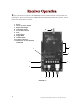
VRX5900 Receiver Operation:
Changing Channels:
To change channels, simply depress the Toggle/Standby switch momentarily until the
LED for the desired channel pattern is lit up. Remember to change the transmitter
channel as well, since it is not automatically changed when the receiver channel is
changed. As a rule of thumb, the first 6 systems operating along the same
transmission path should be set to use even channels ( 2,4,6,8,10,12). If more than 6
systems are required along the same path, use opposite polarization antennas and then
set the units to operate on the odd channels (1,3,5,7,9,11). Contact Trango Tech
Support for additional help on setting the correct configuration for your application.
Alarm Outputs:
When the VRX5900 receives an alarm state change from the transmitter, it will close
or open the corresponding alarm output. The state of the alarm outputs (open or
closed) can be viewed using the TrangoLink software. If the transmitter is in
Standby mode or the transmitted signal is lost, the receiver will hold the last received
valid state of the alarms. The Alarm outputs are dry-contact relays.
RSSI Mode:
To ease alignment of the receiver antenna, the received signal strength may be
viewed by placing the unit in RSSI mode. The LEDs will then act as a bar-graph
indicator, with more LEDs lit for a stronger signal.
To enter RSSI mode, hold down the Toggle/RSSI button for 2 seconds. To exit,
depress the button momentarily. The number of LEDs lit is a relative indication of
signal strength to be used only to find the best antenna position. Viewing the
received picture quality should be used in conjunction with this mode.
Data Pass-Through Mode:
The transmitter and receiver can be used to pass user data one-way from the
VTX5900 to the VRX5900 at rates from 1200 to 9600 bps. (For optimum data
transmission without losses, both the transmitter and receiver should be configured to
pass or accept data at the same rate. The data rate can be configured using the
TrangoLink software.) To enter Data Pass-Through mode, the Stereo/Alarm switch
should be placed in “Alm/Data Mode On.” Then, from the TrangoLink software,
select “Pass-Through Mode.” Make sure both the VTX5900 and the VRX5900 have
been configured for Data Pass-Through mode. The Right Audio channel will be
disabled in this mode while the Left Audio channel can still transmit monaural audio.
Alarms and Link Verification cannot be transmitted when in Data Pass-Through
mode. Do not use CBLDAT-1 to send or receive data since it contains extra wires
not used for normal data transmission.
Please see the pinout diagram in Figure 3 for more information on wiring the data
connector for RS-232.