
User's Manual

Copyright © 1999 Trango Systems, Inc. All rights reserved.
13
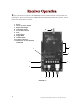
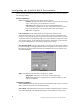
VRX5900 Receiver Inputs/Outputs & Controls:
1. POWER INPUT
Accepts a 6-9 Vdc power source such as the standard 7 Vdc adapter (Trango part
number PT07800-1), or an optional battery. The nominal current draw is 450
milliamperes. If using an adapter from a third party, use a well-regulated 6-
9Vdc/500mA output supply.
2. ALARM OUTPUTS
These are dry contact relay outputs which can sink 1 ampere at 40 V AC/DC. When
the corresponding transmitter alarm input closes or opens, this output will close and
open as well. Consider these outputs mirrors of the transmitter alarm inputs. These
outputs are independent and can be used to turn on peripheral devices such as video
recorders and audible alarms.
3/4. RIGHT & LEFT AUDIO OUTPUTS
Designed to mate to a standard RCA male connector, this provides a 1.5 Volt peak-
to-peak audio output and should be terminated in a minimum 600 Ω load, as is found
in most “line in” audio inputs.
5. STEREO/ALARM SWITCH
When this switch is in the “R Audio On” position, stereo audio transmission is
enabled. This permits the transmission of stereo audio with no data or alarms. When
it is in the “Alm/Data Mode On” position, alarm transmission is enabled. If Data
Pass-Through mode is enabled through the TrangoLink software, the switch must be
set to the “Alm/Data Mode On position.
6. DATA INTERFACE
When connected to a personal computer via the optional CBLDAT-1 interface cable,
this input accepts serial commands that control settings in the receiver not available
via the front panel. See the TrangoLink software program help for more information.
This port is also used for Data Pass-Through mode for RS-232 signal levels.
7. VIDEO OUTPUT
Designed to mate to a standard BNC male connector, this provides a 1 Volt peak-to-
peak video signal output. This must be terminated with 75 Ω. RCA to BNC adapters
are available for use with some monitors and VCR inputs.
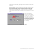
8. TOGGLE/RSSI
To change the receiver channel, depress this switch momentarily. Remember to
change the transmitter channel as well since it is not automatically changed.
To enter RSSI (Received Signal Strength Indicator) mode, hold down this button for
2 seconds. The number of channel LEDs lit is an indicator of signal strength, which
can aid in finding the best antenna position.