
User's Manual

Copyright © 1999 Trango Systems, Inc. All rights reserved.
12
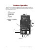
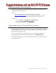
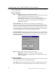
Figure 4 shows the front panel of the VRX5900 receiver and the functions of each control and
input/output. This card is encased in a NEMA-4X rated aluminum/powdercoat enclosure. Do not
remove the card from the enclosure.
1. Power
2. Alarm 1/2 relay outputs
3. Right audio output
4. Left Audio output
5. Stereo/Alarm switch
6. Data
7. Video output
8. Toggle/RSSI
9. Channel LEDs
10. Antenna connector
11. Header for use with optional
LC485/422
• FIGURE 4 •
8.
2.
9.
5.
1.
7.6.4.3.
10.
11.