
User Manual

Copyright © 1999 Trango Systems, Inc. All rights reserved.
4
F
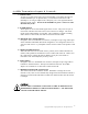
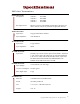
igure 2 shows the interior of the VST2500 transmitter and the functions of each control and
input/output.
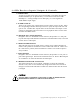
IMPORTANT NOTE: Any modification to the antenna unit may void the user’s
authority to operate the equipment and will void the manufacturer’s warranty.
CAUTION
CAUTIONCAUTION
CAUTION
DO NOT APPLY VOLTAGE TO THE ALARM PINS. DAMAGE TO THE
UNIT WILL RESULT.
1.
Power – 6-12 Volts DC
2.
Alarm 1/2 inputs – DRY
CONTACT ONLY
3.
Right audio input – 1 Vpp 600
Ohm terminated RCA-F
4.
Left audio input – 1 Vpp 600
Ohm terminated RCA-F
5.
Stereo/Alarm switch
6.
Video input – 75 Ohm
terminated RCA-F
7.
Channel DIP switch
8.
Status LED
• FIGURE 2•