
User Manual


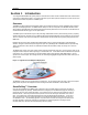

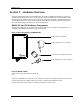
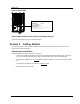
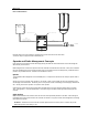
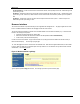

Table of Figures Trango
Trango Broadband Wireless — M900S User Manual Rev. 1A page iii
Table of Figures
Figure 1-1 Typical Point-to-Multipoint Deployment..............................................................................................................................1
Figure -2-1 Basic Components of an M900S Radio ............................................................................................................................3
Figure 2-2 Bottom of Radio..................................................................................................................................................................3
Figure 2-3 Back of Radio .....................................................................................................................................................................4
Figure 2-4 Side of Radio & Location of Reverse Polarity SMA Connector..........................................................................................4
Figure 3-1 Wiring Diagram...................................................................................................................................................................5
Figure 3-2 Browser Interface Login Page ............................................................................................................................................6
Figure 3-3 Web Browser System Information Page.............................................................................................................................7
Figure 4-1 Bottom of M900S Radio with LEDs ..................................................................................................................................14
Figure 5-1 Reference Table of Basic AP System Information ...........................................................................................................18
Figure 5-2 Reference Table of Basic SU System Information ...........................................................................................................20
Figure 6-1 M900S Mounting Hardware Assembly ............................................................................................................................23
Figure 6-2 Alternative Mounting........................................................................................................................................................23
Figure 6-3 Articulation for M900S with Mono Pod Mount (not supplied) ...........................................................................................24
Figure 6-4 Grounding Example..........................................................................................................................................................24