
User Manual


Copyright © 1999 Sunstream Wireless, LLC All rights reserved.
8
1) Keep the transmission path as open as possible. Objects such as walls and metallic
objects near the transmission path reflect signals and may reduce the transmission
distance.
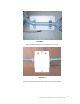
2) Mount the transceiver on the mounting pole as shown in Figure 1.
3) Connect the STP run no longer than 300 feet (when using a 24 Volt supply), 150 feet
if using the standard 20 V supply– Use straight through 8 conductor cat 5 cable, making
sure that the RJ45 terminations are shielded.
4) Use standard outdoor to indoor drip loop and grounding per National Electrical Code
and electrical conduit if appropriate.
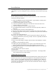
5) Connect the Junction Box to an interior wall near the entry point of the cable.
6) Plug the STP cable into the ODU port of the Junction Box.
7) Plug the wall mount power adapter into the Junction box.
8) Plug the wall mount adapter into the wall outlet.
9) The LEDs on the Junction box should both be on, indicating that the power is coming
into the junction box properly and that the outdoor transceiver is powered up properly.
Check the wiring if this is not the case.
CONNECTION VERIFICATION
After the alignment is completed, an Ethernet cable can be connected to the “NET” port
of the Junction Box and then to a switched hub or PC network card. A crossover cable
will be required if connecting to a PC NIC.
M5800SB-AP-60 Inputs and Outputs
1. POWER INPUT
Accepts a 10.5-24 Vdc power source such as the standard 20 Vdc adapter (supplied
with Sunstream part number ODU-PKIT-1).
2. ETHERNET DATA INTERFACE
Use a shielded cat 5 cable to connect the junction box to the transceiver unit. It is ok
to us UTP for the indoor connection to the switch or PC.
4. LED INDICATORS
These LEDs indicate when a data packet is transmitted(red) or received (green). The
yellow LED indicates the strength of the signal received from the base station.