
User Manual


Copyright © 1999 Sunstream Wireless, LLC All rights reserved.
7
Installation:
Typically the service provider will program the transceiver and professionally install the
entire system. If you are installing the system yourself, below you will find a step by step
guide.
TRANSCEIVER SETUP PRIOR TO INSTALLATION
Before installing the hardware you must set up the transceiver to allow communication
with the the subscriber database.
1) Obtain the M5800S-AP Series Wizard program, .cfg file diskette, and Setup cable
(CBLDAT-1) from your service provider.
2) Load the wizard program onto a PC or Laptop
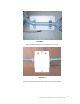
3) Connect the junction box ODU port to the transceiver with a short section of 8
conductor UTP cat 5 network cable.
4) Connect the CBLDAT-1 to the PC or laptop serial port.
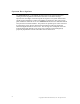
5) Use a Philips head screwdriver to remove the access door temporarily. Inside is an
RJ11 jack
6) Connect the phone connector end into the RJ11 jack.
7) Plug the power adapter into the junction box and then into a 120 VAC wall outlet.
8) Wait 30 seconds for the unit to power up. The LEDs on the junction box should both
be glowing solid.
9) Click on the wizard program icon.
10) Click on the “Serial Port” button, choose the appropriate COM port, and enter the
password (obtained from your service provider). If none was provided, the default is
“sunstream”.
11) Click the “Connect” button.
12) The screen should change to a display with the notation “PG-SYSINFO” at bottom
right.
13) Click the “Load Configuration” button.
14) A dialog box pops up prompting for the .cfg file. Locate the default.cfg file on the
diskette provided or download it from the web. Highlight it and click “open”
15) The program should return to the PG-SYSINFO page and show the new values just
loaded from the .cfg file.
16) Click “Reboot Unit” and wait 1 minute.
17) Click “Quit”
18) The unit is now ready for service and may be powered down . All settings loaded
will be retained in the non-volatile memory.
HARDWARE INSTALLATION
Mount the transceiver units above human and mechanical traffic, aiming it in the general
direction of the service area. In general, the higher above the ground the antenna is, the
better. A 10 foot 2 3/8” diameter steel mast on top of a building is typical. Make sure
that the mast is well grounded to earth ground with an 8 AWG or larger wire. For best
performance, the antenna must be 15 to 20 feet above all obstacles in the line of sight to
the any one subscriber unit.