
User Manual

Access Point Manual Page 5 of 9
SunStream Wireless, a division of Trango Systems, Inc. Copyright © 2001
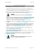
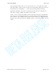
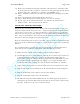
FIGURE 1
An Access Point radio properly attached. There is a single CAT5 cable that provides power and data
to the Access Point. The Access Point is mounted to a pole using an optional pole mount bracket.
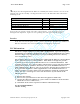
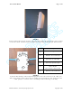
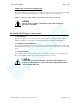
Symbol Description
A
Mounting Hole
B
LED ON = Access Point OK
C
ODU Port – connects to AP
(RJ45 Port w. CAT5 UTP)
D
Power Port (20 Vdc input)
E
NET Port – connects to Switched
Hub or PC NIC
(use crossover cable for PC)
F
LED ON = Junction Box OK
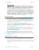
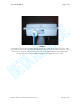
FIGURE 2
A Junction Box showing a CAT5 straight-through power/data cable connected to the “ODU” port
with a power adapter cable connected to the “PWR” port and an Ethernet cable connected to the
“NET” port (use a crossover cable at the NET port when connecting to a PC NIC).
F
E
A
B
C
D
A
NET
ODU
PWR